Section 7.1 · Topic 1 of 10
7.1.1 Waveguides
Waveguides are structures through which electromagnetic waves propagate and electromagnetic power is transferred efficiently from one point in space to another. In practice, the choice of structure depends on
- the desired operating frequency band,
- the amount of power to be transferred, and
- the amount of transmission losses tolerated.
What is new compared with Chapter 6 is that the wave is now confined sideways by conductors (or, in Section 7.6, by a dielectric). The fields must satisfy the boundary conditions on the walls, and only certain field patterns fit between them. These patterns are the modes of the guide, and each mode travels only above its own cutoff frequency.
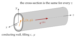
Figure 7.1.2 shows the three kinds of guide met in the rest of this chapter. They look very different, but they have one property in common: all of them are uniform along the direction of travel. That single property is what the analysis of this section uses.
- Rectangular and circular waveguides (Sections 7.3 and 7.4) are single hollow conductors. They carry TE and TM modes only, each above a cutoff frequency, with low loss and high power: radar, satellite ground stations, particle accelerators.
- Coaxial cables (Section 7.5) have two conductors. They carry a TEM wave from dc upwards, and higher modes appear only at high frequency. This is the everyday RF cable.
- Microstrip lines (Section 7.7) are printed strips over a ground plane, two conductors in two dielectrics, and carry a quasi-TEM wave. They are cheap, planar and easy to integrate with circuits.