Section 7.3 · Worked examples · 2 of 3
Worked example 7.3.2: A slotted-waveguide array for a marine radar
About the worked examples of Section 7.3
Three short calculations tied to the applications, with , , , the power limit and the copper loss of the TE mode, and no new physics. Constants: , , copper , breakdown of dry air . A good way to use them: read the given quantities, produce the formula from the corresponding application yourself, and only then put the numbers in.
A slotted-waveguide array for a marine radar
#Given. A long WR-90 guide () with longitudinal slots on alternate sides of the centre line, spaced at the design frequency , shorted at the far end.
Find. (a) , and , (b) the number of slots and the beam width (uniform excitation), (c) the phase step and the beam direction at and , (d) the position of the short.
Adjacent slots are apart, so the guide wave reaches them apart, and alternating the side of the centre line adds another : at all slots radiate in phase. A uniform array of length has , and a phase step between elements tilts the beam to .
, and :
, so slots and :
The spacing stays while changes:
The short must place a maximum of the standing wave at the last slot: beyond the centre of the last slot.
At , exactly, so and the beam is broadside. The sign is right: above the guide wavelength shrinks, the phase per slot exceeds and each slot lags its predecessor more, which tilts the beam towards the load end.
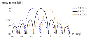
A change tilts the beam by more than its own width (Figure 7.3.20): the array is a narrow-band antenna. Used on purpose, the same effect gives frequency-scanned radars that steer the beam without moving parts. Real arrays taper the slot offsets for low side lobes, which widens the beam a little.
cf. Application 7.3.2