Section 5.5 · Topic 5 of 12
5.5.5 The speed of the wave
In a simple lossless medium with and the speed Eq. (5.5.10) is
In free space, with the constants of this course,
The number is the refractive index of the medium. For the nonmagnetic media of most of this course .
Every material slows the wave: whenever . The speed depends only on the two material constants that measure how strongly the medium answers an electric and a magnetic field.
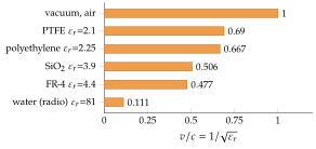
Figure 5.5.4 shows the speed in a few common nonmagnetic insulators. Water at radio frequencies, with , slows the wave to . The plastics of cables and the glass fibre of printed circuit boards give between about and .
The number comes from electrical measurements. W. Weber and R. Kohlrausch determined it in 1856 by comparing the charge of a capacitor, measured electrostatically, with the same charge measured by the kick it gave a galvanometer when discharged. Maxwell saw in 1862 that the result agrees with the measured speed of light and concluded that light is an electromagnetic wave (Figure 5.1.1 in Section 5.1). Today the logic runs the other way: is defined exactly and fixes the metre (Exercise 5.1.2).
A wave travels at in a nonmagnetic dielectric. What is , and what is the speed in distilled water with ?
(polyethylene). In water , nine times slower than in vacuum.
A digital edge or a microwave signal travels along a printed circuit trace or a cable as an electromagnetic wave in the insulator around the conductors. The conductors only guide it. When the whole field sits in one dielectric, as in a stripline (a trace buried between two ground planes) or a coaxial cable, the wave travels at the speed of this section, and a line of length delays the signal by (Figure 5.5.5):
On a microstrip (a trace on top of the board) part of the field is in the air above the board, and is replaced by an effective value between and (Section 7.7).
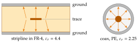
Table 5.5.1 lists the speed and the delay per millimetre for the media of Figure 5.5.4. The delay per millimetre is , in air and about twice that on a board.
Table 5.5.1. Speed and delay per unit length on lines whose field lies in one dielectric.
| Medium | [m/s] | delay [ps/mm] | |
|---|---|---|---|
| vacuum, air | |||
| PTFE cable | |||
| PE cable | |||
| SiO on a chip | |||
| FR-4 board |
When is a wire not just a wire? A digital edge of rise time occupies the length of the line. If the line is much shorter than that, the voltage is practically the same along it at every instant and the line is an ordinary wire of circuit theory. Once the one-way delay exceeds a fraction of (a common rule of thumb is ), the two ends see different voltages at the same moment, reflections at the ends become visible, and the trace must be designed as a transmission line with a controlled impedance and a matched termination.
Typical numbers. A edge is long on FR-4. One period of a clock, , is . A skew budget in a differential pair allows only of length mismatch between its two traces, which is why boards show serpentine traces. Worked example 5.5.1 puts these numbers together, and Exercise 5.5.2 locates a cable fault by the delay of its echo.