Section 6.3 · Topic 6 of 8
6.3.6 Quarter-wave and half-wave layers
It is more natural to refer the reflection to the front face , where the reflected and the incident waves meet:
The transmission-line picture now gives in one line. Look from medium 1 into the layer and ask for the ratio of the total to the total at the front face, the input impedance (both fields taken with the reference directions of the incident wave). With Eq. (6.3.30),
Their ratio is the input impedance. On the medium-1 side of the front face the same ratio is , and the continuity of and makes the two equal.
A layer of impedance and thickness in front of medium 3 presents to medium 1 the input impedance
at its front face. This is the input impedance of a transmission line of length and characteristic impedance terminated by the load .
Seen from the front, the layer and everything behind it act like one medium of impedance . The layer transforms the impedance into , and the transformation depends on how many wavelengths thick the layer is.
Quarter-wave layer
For , and . Dividing numerator and denominator of Eq. (6.3.39) by gives . The reflection vanishes, , if
A quarter-wave layer whose impedance is the geometric mean of its neighbours removes the reflection completely. Two equal echoes, one from each face, come back half a wavelength apart and cancel.
Half-wave layer
For (or any multiple), and : the layer disappears, whatever is. With there is no reflection at all, which is the half-wave window of case (i) above.
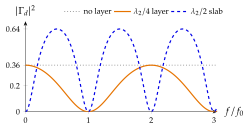
is the design frequency. Away from it the electrical thickness (or for the half-wave slab) changes, moves away from its design value and the reflection grows (Figure 6.3.7). The bandwidth over which a single layer works is the subject of Problem 6.3.5, Home exercise 6.3.4 and Exercise 6.3.4.
The coating of Problem 6.3.4 below (, on glass with ) is designed for . Drag along the lower plot from to and see the reflection rise from to .
Light of nm falls normally from air on a substrate with . Which single layer removes the reflection?
and nm.
Making the layer thick. The quarter wave is measured in the layer: , shorter by the factor . Likewise in Eq. (6.3.39) uses , never .
Reflection is a nuisance (glare, lens flare, lost solar power, mismatched radomes) and a resource (mirrors without metal, light guides, polarisers). The layer results of this section are the engineering answer to the nuisance, at optical and at microwave frequencies alike.
The quarter-wave coating. Bare glass () reflects per surface. A camera lens with ten glass surfaces in air would lose a third of the light () and fill the image with ghost reflections. A layer of thickness on the glass sends back two waves (1 and 2 in Figure 6.3.8a): wave 2 has travelled an extra round trip through the layer, so it comes back half a wavelength behind wave 1, and the two cancel when their amplitudes match. The two faces reflect equally, , exactly when , the condition Eq. (6.3.40):
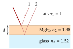
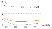
The ideal has no durable material. Magnesium fluoride, MgF (, nm for nm), leaves
nearly flat over the visible (Figure 6.3.8b). Multilayer stacks reach below . On solar cells the coating is silicon nitride, SiN, and the gain is far larger because bare silicon reflects a third of the light (Worked example 6.3.1).
The half-wave radome. An antenna cover, a radome, must protect the antenna from the weather without reflecting its radiation. A wall of thickness
has and is transparent at its design frequency: for at GHz ( mm) mm. Thin walls () are the broadband option, since in Eq. (6.3.36) stays small while is small. Problem 6.3.5 designs a radome wall that must also be mechanically strong, and Worked example 6.3.2 treats an ordinary window pane as a (non-designed) radome for Wi-Fi signals.
Why does a radome wall work for any permittivity when it is thick, whereas a coating needs the right index?
At a half-wave wall the two echoes have opposite signs automatically (air to dielectric gives , dielectric to air , with equal magnitudes) and a full round trip, so they cancel whatever the impedance step. In a coating the two faces see different impedance steps, and only makes them equal.
Table 6.3.1. The application of this section and where it is worked out.
| Application | Physics used | Worked out in |
|---|---|---|
| Antireflection coatings | , | Worked example 6.3.1, Problem 6.3.4, Home exercise 6.3.4 |
| Radome windows | , of a slab | Worked example 6.3.2, Problem 6.3.5 |