Section 7.8 · Topic 16 of 18
7.8.16 The directional coupler
A directional coupler is a four-port that separates the power travelling forwards from the power travelling backwards (Figure 7.8.20). Port 1 is the input, port 2 the through port, port 3 the coupled port and port 4 the isolated port. It is used in reflectometers, power meters and standing-wave measurements, and it is specified by two numbers:
the coupling and the directivity. The directivity compares the power that reaches the coupled port from a forward wave with the power that reaches it from an equal backward wave. The isolation, , is how far below the input the isolated port stays.
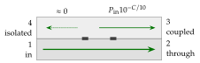
Ports 1 and 4, and ports 2 and 3, are decoupled.
Definition Eq. (7.8.41) compares the coupled-port power for equal forward and backward waves. The datasheet form for a forward wave alone is the same number for a symmetric coupler.
How a two-hole coupler works
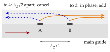
Each hole in the common wall couples a small wave into the upper guide, travelling both ways (Figure 7.8.21). With holes A and B a quarter guide wavelength apart:
- towards port 3 both coupled waves have travelled the same total path, and they add,
- towards port 4 the wave from B has travelled further than the wave from A, and they cancel.
The cancellation is perfect only at the design frequency. With the spacing and the phase constant at another frequency,
If is off by , drops to about . Many holes with binomial strengths give broadband couplers (Exercise 7.8.9).
Waveguide couplers have to and to over a waveguide band. Their through loss is , only for a coupler. Problem 7.8.5 shows what a finite does to a measurement.
Using as the level of the coupled signal. The coupled port sits below the input. A wave travelling the wrong way reaches it below the input, and the isolated port receives the same from the forward wave. A coupler with directivity therefore delivers of the forward power to port 3, and the leakage that spoils a reflection measurement is , not , below the line power.