Section 7.8 · Topic 2 of 18
7.8.2 From a shorted waveguide to a cavity
We need only a few results of the guide analysis (Sections 7.1 and 7.3). A mode of a uniform guide filled with a homogeneous medium has a transverse pattern and travels as , with fixed by Eq. (7.8.1). In the rectangular guide the cutoff wavenumbers are
and the dominant TE mode has and . For a TM mode the transverse electric field follows from the longitudinal one. For a wave travelling along it is , and for a wave travelling along the sign of changes, .
Now close the guide by conducting walls at and . A mode travelling along is reflected by the wall at , the reflected mode is reflected again at , and the field inside is the sum of the two travelling waves. For a TM mode,
The minus sign inside the second bracket is the change of sign of with the direction of travel. The end walls are perfect conductors, so the tangential electric field, which is , must vanish on them. At this requires , and then
since . The wave has become a standing wave: has a node on the wall and , normal to that wall, a maximum. At we need as well, that is .
The two end walls allow only the phase constants
where is the guide wavelength. The end walls sit at nodes of the transverse electric field, a whole number of half guide wavelengths apart.
A cavity is a piece of guide whose length fits the standing wave exactly. Lengthen it by half a guide wavelength and another standing wave fits, at the same frequency, with one more half-period along .
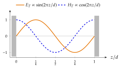
The same reasoning holds for every component and for TE modes as well, and it gives a rule that we shall use all the time.
The components that must vanish on the end walls, the transverse and the normal (), vary as . The components linked to them by one derivative vary as . These are and for TM modes and for TE modes. Figure 7.8.2 shows the pattern for . Electric and magnetic maxima are a quarter of a guide wavelength apart, as in the standing wave in front of a conducting plane (Section 6.3).