Section 7.8 · Worked examples · 2 of 3
Worked example 7.8.2: An X-band TE_{011} wavemeter
About the worked examples of Section 7.8
Three short calculations tied to the applications, with resonant frequencies, , bandwidth, stored energy and wall loss. They use only the results of this section. A good way to use them: read the given quantities, produce the formula from the corresponding application yourself, and only then put the numbers in. Constants: , , , copper , , .
An X-band TE wavemeter
#cf. Application 7.8.2
Given. A copper cylinder, , air. The length is set by a non-contacting plunger driven by a micrometer with divisions. Weak coupling to WR-90.
Find. (a) the TE cutoff and the plunger setting for , (b) and the width of the dip, (c) the tuning slope and the frequency step per division, (d) the range for to , (e) why the degenerate TM does no harm.
TE is TE of the circular guide () with one half guide wavelength between the end plates: . Its fields, Eq. (7.8.34), , and , give with
where . The side wall carries , the end plates . With ,
. At and :
, , and :
From ,
One division () is , five times the dip width.
: . : . The range is to (Figure 7.8.28).
TM has and resonates at the same frequency, but its wall currents flow along and must cross the gap around the plunger. They are interrupted, its collapses and it produces no visible dip. TE has only -directed currents, which never cross that gap.
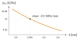
. The finite difference over the whole range is close to the slope at the centre.
The micrometer, not , sets the resolution here: about , ample for checking an X-band source. A finer scale would only help down to the dip width, .