Section 7.4 · Topic 7 of 11
7.4.7 Cutoff frequencies and the order of the modes
The cutoff frequency of Section 7.1 now follows from Eq. (7.4.16) and Eq. (7.4.19).
A mode propagates only if , with . The dominant mode is TE, the mode with the smallest zero, :
The wall must sit at a zero of (TM) or of (TE). A small zero means a small and a low cutoff. The smallest zero of all, , belongs to , so TE is the first mode to propagate. For an air-filled pipe .
Sorting all the zeros gives the order of the modes in Table 7.4.2 and the cutoff chart of Figure 7.4.4. The cutoff wavelengths are (TE), (TM), (TE) and (TE and TM).
Table 7.4.2. The first modes of a circular guide in the order of their cutoffs, with the zero that fixes the cutoff. “Copies”: the and versions of each mode with , two independent field patterns.
| mode () | copies | ||
|---|---|---|---|
| TE () | |||
| TM () | |||
| TE () | |||
| TE () | |||
| TM () | |||
| TE () | |||
| TM () |
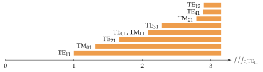
Three facts stand out.
- The single-mode band is narrow. Only TE propagates for , a band of , against for a rectangular guide with (Section 7.3).
- Even there TE is a pair. Its and copies have the same , and a slight ellipticity or a bend of the pipe turns its polarisation.
- TE and TM share their cutoff, because makes . Modes with the same cutoff are called degenerate. They have the same phase velocity at every frequency and convert into each other at bends without any phase mismatch to stop it.
A circular guide is not chosen for its bandwidth. It is chosen for its symmetry: TM does not depend on and passes through a rotating joint unchanged, TE carries two independent polarisations, and TE has a loss that falls with frequency. The three applications of this section and of Section 7.5 rest on exactly these properties.
The tool below shows the pipe of Problem 7.4.1 (). Tap the bars of its cutoff chart in order, TE, TM, TE and TE/TM, and see where each wall condition puts the wall on the Bessel curve.
An air-filled pipe has cm. In which band is it single-mode?
GHz and GHz: single-mode from to GHz, a ratio of .
In a rectangular guide the dominant mode is TE, and the habit of “the mode with a zero index” suggests TE for the round pipe. But the indices mean different things here: TE of a circular guide has and starts at times the TE cutoff, as the sixth field pattern to propagate. The round counterpart of the rectangular TE is TE, with one period around the pipe.