Section 7.4 · Topic 8 of 11
7.4.8 Field patterns
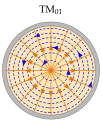
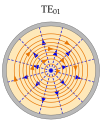
Figure 7.4.5 shows the transverse fields of the three most important modes in the cross-section , at the instant when the transverse fields are real. The patterns were computed from Eq. (7.4.17) and Eq. (7.4.20). For a TE mode the transverse electric field is , so the lines are the contour lines of , and follows the gradient lines. For a TM mode the roles are exchanged: and the lines are the contours of . The contours are drawn at equal steps of (or ), so that their density follows the field strength.
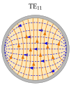
- TE, the dominant mode. In the middle of the guide is almost uniform and vertical. Towards the wall the lines bend and meet the metal at right angles, ending on surface charge at the top and the bottom. It is the round relative of the rectangular TE, and a rectangular guide can be tapered smoothly into a circular one carrying TE.
- TM is rotationally symmetric: is radial, with an axial component largest on the axis, and circles around the axis. Nothing depends on , which is why it is used in rotary joints (Application 7.4.1).
- TE is rotationally symmetric as well: circles around the axis and vanishes at the wall, is radial in the cross-section, and at the wall only is left. The wall current is then purely azimuthal, the key to its low loss (Section 7.4.9).
The dominant TE₁₁ mode and its two polarisations
Near the axis (the series of the box in Section 7.4.2), so . With the TE fields Eq. (7.4.20) give
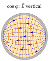
since . The field is uniform across the middle of the guide, as in TE. The version has along , the version has along , and both have the same (Figure 7.4.6). Any superposition of the two propagates unchanged:
With the two patterns are in time quadrature and the mode is circularly polarised: the whole pattern turns once per period, exactly as the field of a circularly polarised plane wave (Section 6.1).
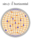
Satellite feeds carry two independent signals, vertical and horizontal or right- and left-hand circular, in one short round pipe (Worked example 7.4.1). The same degeneracy is a nuisance in long runs: in a slightly elliptical or bent pipe the two copies travel at slightly different speeds and the polarisation drifts along the guide (Exercise 7.4.3 turns this drift into a useful device). Long runs therefore use rectangular guide, whose TE has a single fixed polarisation.