Section 7.5 · Topic 6 of 8
7.5.6 Higher-order modes and the upper frequency limit
Besides the TEM wave the coaxial line supports TE and TM modes, built exactly as in the circular pipe of Section 7.4, with one difference: the field region is now the annulus . The axis is inside the inner conductor, the singularity of at is outside the region, and both solutions of Bessel's equation, Eq. (7.4.9) in Section 7.4, must be kept. For the TE modes take
The combination is chosen so that vanishes at : the condition on the inner conductor is built in. On the outer conductor, at gives the characteristic equation
a transcendental equation for that is solved numerically. (For TM modes the same steps with on both walls give .) Its lowest root belongs to TE, the first higher mode of the coaxial line, and lies very close to a simple estimate.
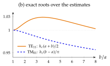
The coaxial line is single-mode (TEM only) below . The exact root of Eq. (7.5.16) is at most above the estimate for .
TE is the TE mode of a rectangular guide bent into a ring. It needs one full period of around the mean circumference , so it starts when the wavelength in the dielectric has shrunk to that circumference. The thinner the cable, the higher it can go.
If the gap is narrow, , the field hardly varies across it, and everywhere in the gap, not only at the walls. Bessel's equation, Eq. (7.4.8) in Section 7.4, then reduces to its last term, , evaluated at the mean radius :
The mode fits wavelengths around the mean circumference, like a TE mode of a rectangular guide of width bent into a closed ring. The surprise is how good the estimate stays for wide gaps: Figure 7.5.5b compares it with the exact roots of Eq. (7.5.16). The first TM mode, TM, needs instead half a period across the gap, like the TE mode of a narrow guide of width : , within for . For its cutoff is times that of TE: in a line TE is by far the first intruder.
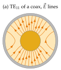
Above a second mode, with its own phase and group velocities, can carry part of the power. Any discontinuity (a connector, a bend, a support bead) converts some TEM power into it, and the signal is distorted. Every cable and every connector therefore has an upper frequency limit set by Eq. (7.5.17), and the only way to raise it is to make the line smaller, which raises the loss ( at fixed ).
The precision mm air line ( mm, mm) is rated to GHz. Why not higher?
GHz (the exact root gives GHz). Above that TE can propagate, so the rating stops just below. Exercise 7.5.2 shows that the support beads lower the limit further.
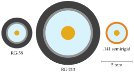
Every laboratory bench is cabled with coaxial lines, and the formulas of this section explain their data sheets. Table 7.5.1 applies them to five standard cables, with smooth copper, polyethylene () or PTFE (), both with . Figure 7.5.6 draws three of them to scale.
Table 7.5.1. Standard coaxial cables computed with the formulas of this section: from Eq. (7.5.8), the loss at GHz from Eq. (7.5.13) and the TE cutoff from the estimate Eq. (7.5.17). SR: semirigid (solid copper tube). PE: polyethylene. Stranded inner conductor, nominally . Measured losses of braided cables are higher.
| cable, [mm] | [] | at GHz [dB/m] | [GHz] |
|---|---|---|---|
| RG-58 (PE), | |||
| RG-213 (PE), | |||
| .141 SR (PTFE), | |||
| .085 SR (PTFE), | |||
| .047 SR (PTFE), |
The key formula of the application is the frequency limit
: thinner cable, higher limit, more loss
Precision connectors. Laboratory connectors are air lines with , named after their outer diameter . Their TE cutoffs, from the exact root of Eq. (7.5.16), set their ratings:
| [mm] | [GHz] | rated [GHz] |
|---|---|---|
Each stops below its TE cutoff, and the dielectric support beads lower the limit further: GHz measurements need mm parts, GHz needs mm parts. Worked example 7.5.1 compares two cables for a mast and shows why millimetre-wave radios are mounted at the antenna.