Section 7.6 · Topic 12 of 14
7.6.12 Modal and chromatic dispersion
Modal dispersion
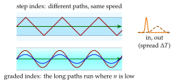
In a multimode fibre each mode, in the ray picture each ray angle, has its own delay. All rays travel at the same speed in a step-index core, but along paths of different length. The axial ray covers the length of fibre in . The ray at the critical angle runs the path and needs . A short pulse that excites all modes is therefore spread over
Consecutive bits stay apart if ( the bit rate), which limits the product of the bit rate and the length:
In a step-index fibre the steep rays take the long way round and arrive late. The spread grows with the length and with the index step, so a multimode fibre is either short or slow.
Saying that the higher modes "travel more slowly". In the ray picture of a step-index core every ray travels at . The steep ray is late only because its path is longer by the factor . In the mode picture the same fact appears as a group velocity that differs from mode to mode.
Graded index
The remedy for multimode fibres is a core whose index falls gradually from on the axis to at the core boundary (Figure 7.6.11). The long, steep paths now run through the outer core, where the index is low and the light is fast, and the short axial path runs where the light is slow. With the optimum profile, very nearly parabolic, the delays become almost equal:
which is times smaller than Eq. (7.6.39): for , eight hundred times.
For the exactly parabolic profile the ray picture can be solved exactly. A meridional ray keeps the invariant ( its angle with the axis), the ray equation makes an exact sinusoid (Orfanidis, Example 7.15.7), and the time of flight per unit length, , averaged over one period, is . Between the axial ray () and the ray that just reaches the core boundary () the delays differ by
already times less than the step index. A profile slightly flatter than the parabola, with , also cancels the next term of the expansion. The mode analysis of this optimum profile (Olshansky and Keck, 1976) gives the four times smaller spread Eq. (7.6.41). Real fibres come close to it but not all the way.
Chromatic dispersion
A single-mode fibre has no modal dispersion, but the source is never perfectly monochromatic. Its spectral width contains components that travel at slightly different group velocities, because the index of silica, and with it the mode, depends on the wavelength. The pulse spreads by
where the dispersion parameter of standard fibre is close to zero at and about at .
For the step-index fibre of Problem 7.6.4 ( core, , ), Eq. (7.6.39) gives and . A graded-index fibre with the same indices has and .
Nearly all long-distance data, the internet backbone, undersea cables and mobile backhaul, travel as light in single-mode silica fibre. Two properties of the glass decide where in the spectrum. Silica scatters light by Rayleigh scattering on frozen density fluctuations, which falls as , and it absorbs in the infrared, beyond about , by vibrations of the Si–O bond. Between the two lie the low-loss windows (Figure 7.6.12 and Table 7.6.2).
Table 7.6.2. The three windows of silica fibre (typical values).
| Window | loss [dB/km] | [ps/(nm km)] | Use |
|---|---|---|---|
| nm | large | buildings (multimode) | |
| nm | access and metro links | ||
| nm | long haul |
Single-mode against multimode. Single-mode fibre (, ) has no modal dispersion. It carries to per wavelength, dozens of wavelengths per fibre (wavelength-division multiplexing, WDM), and erbium-doped fibre amplifiers (EDFA, to ) restore the signal every to . Multimode graded-index fibre ( core) accepts cheap surface-emitting lasers and easy connectors. Its modal dispersion limits it to a few hundred metres at , which is enough inside a data centre. The link budget is written in decibels, where every loss is subtracted:
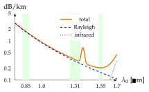
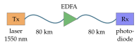
Worked example 7.6.1 puts numbers on an span. It shows the trade-off that shapes every link: the loss favours , the dispersion favours , and long-haul systems take and manage the dispersion.
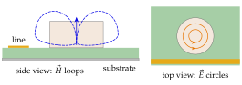
A short cylinder, a "puck", of low-loss ceramic with to is a piece of dielectric waveguide that reflects back on itself. At its faces the index ratio is , so a wave inside meets them far beyond the critical angle () and is trapped, as in the slab, with an evanescent field outside. The puck becomes a resonator, like the metal cavities of Section 7.8, but without walls. Its lowest mode, TE, has circular lines in the puck, and an field that loops through the puck and closes outside, like the field of a small magnetic dipole (Figure 7.6.13).
The resonance frequency of the TE mode of an isolated puck of radius and height is well described by the empirical formula of Kajfez (accuracy about for and , and in millimetres):
Engineers like dielectric resonators for four reasons.
- Size. All dimensions scale with the wavelength in the ceramic, , so the volume falls as : about times smaller than an air-filled metal cavity at the same frequency (Worked example 7.6.2).
- Quality factor. Most of the energy is in the low-loss ceramic, and .
- Stability. The temperature coefficient of is tailored by the ceramic recipe to .
- No walls. The field is held by the dielectric, so the puck can sit on a circuit board.
In a dielectric-resonator oscillator (DRO) the puck sits beside a microstrip line, couples to it through its evanescent magnetic field, and fixes the frequency of a transistor oscillator: the and local oscillators of satellite-TV receivers are the classic example. Several pucks in a metal box form the filters of mobile base stations, and a puck without the box radiates: the dielectric resonator antenna.