Section 7.7 · Topic 7 of 10
7.7.7 Losses of the microstrip line
Conductor loss
At microwave frequencies the current flows in a skin of depth on the conductors, which have the surface resistance (Section 6.2). The current crowds on the underside of the strip and on the ground directly beneath it. As a first estimate let the current spread evenly over the width on both, with the surface current density . The power lost per unit length is then , while the line carries . Since the power decays as , :
Dielectric loss
Only the field in the substrate is lossy. For a line completely filled with a dielectric of loss tangent the attenuation is . In the microstrip the same holds with only the part of the electric energy that is stored in the substrate:
The filling factor runs from (all the energy in air) to (all in the substrate).
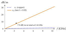
Copper loss grows as and falls with a wider strip. Dielectric loss grows as and depends on the substrate alone. On a lossy substrate like FR-4 the dielectric wins at all radio frequencies.
The power lost in the substrate is , with the time-average electric energy per unit length in the substrate. In a TEM-like wave the electric and magnetic energies are equal, so the transported power is . Hence , with . To first order a change of changes the capacitance by the energy stored in the substrate, so . Hammerstad's , Eq. (7.7.4), is linear in , , and , which is Eq. (7.7.11). Orfanidis's Eq. (11.3.10) is the same result.
Radiation
Bends, open ends and steps in width radiate, and the radiated power grows roughly as : thin substrates radiate less.
Figure 7.7.6 shows both losses for the FR-4 line. At , and . A low-loss laminate (RO4003C, , , ) loses : less dielectric loss, but more copper loss on the narrower strip. Rough copper raises further in practice.