Section 7.7 · Topic 8 of 10
7.7.8 Dispersion and higher-order modes: the frequency limit
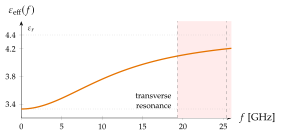
The quasi-TEM picture holds while . As the frequency rises the field concentrates in the substrate, under the strip, and rises from its static value towards : the line becomes dispersive. Getsinger's model describes this with two parameters:
At the correction has done roughly half of its work. For the FR-4 line (Figure 7.7.7).
Upper limits
Two mechanisms end the useful range of a line, both set by the cross-section dimensions compared with the wavelength in the substrate.
-
The TE surface wave of the substrate. The grounded substrate is the coated conductor of Section 7.6.9, and by Eq. (7.6.32) in Section 7.6 with and its TE mode starts at
Above it the line couples strongly to a wave that spreads over the whole board.
-
The transverse resonance of the strip: a field that is half a wavelength across the strip and its fringe, at
The TM surface wave has no cutoff at all (Section 7.6.9), and the coupling to it grows with . The design rule is to keep : thick FR-4 below a few gigahertz, GaAs at .
Controlled impedance. Every trace that carries a radio signal, or a digital edge faster than its travel time along the board, is a transmission line. The board house is asked for "": on the usual FR-4 that means , on a inner prepreg . The tolerance comes from (the glass weave), from and from the etched width (Exercise 7.7.2).
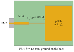
Patch-antenna feeds. A patch antenna is a wide microstrip section about long that radiates from its two open edges. Its edge resistance is a few hundred ohms, and a quarter-wave transformer (or an inset feed) matches it to the line (Figure 7.7.8 and Worked example 7.7.1). GPS, Wi-Fi and phased-array radar tiles use it.
When FR-4 is not good enough. costs at and at . Radio front ends and radar boards therefore use PTFE or hydrocarbon laminates (), bonded in the same multilayer board to cheap FR-4 layers for the digital part. Above thin laminates, alumina and GaAs chips take over.