Section 7.6 · Topic 9 of 14
7.6.9 Surface waves along a dielectric-coated conductor
A dielectric layer of index and thickness on a perfectly conducting plane, with air (or any medium of index ) above it, is a guide for surface waves: waves bound to the surface and decaying away from it. Its modes follow from the slab by image theory. The perfect conductor requires on its surface. A slab mode of thickness that already has on its midplane is undisturbed if a metal sheet is placed there, and conversely the metal and its mirror image of the coating reproduce such a mode (Figure 7.6.8), much as the image charges of Section 3.4.8 reproduce the field above a grounded plane. Which slab modes qualify?
- TE: requires , the odd TE ().
- TM: (Eq. (7.6.15)) vanishes at for , the even TM ().
The normalised frequency is that of the full slab, now with :
The modes appear in the order TM, TE, TM, TE, …, with cutoffs at .
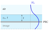
A metal plane with a dielectric coat is half of a slab. It keeps the half of the slab modes whose electric field is perpendicular to the metal, and it guides the lowest TM wave at every frequency.
Surface impedance
Seen from the air, the coated surface presents a reactance. For a TM wave, at the height above the coating and, by Eq. (7.6.15), . The ratio of the tangential fields that points into the surface (power flowing in the direction) is
A purely reactive surface absorbs no power, and the wave travels along it without loss. Cheng derives the same two impedances for the slab, his Eqs. (10-261) and (10-279), and concludes that an inductive surface supports TM surface waves and a capacitive one TE surface waves.
For the TM root lies near the origin of the – plane: , so , and with (since ),
which is Cheng's Eq. (10-283) for a slab of thickness . A thin coat binds the wave only loosely: and . For PTFE (), , at () the estimate gives , close to the exact root : the field reaches into the air, and .
A wire with a dielectric coat guides the TM surface wave (the Goubau line, used for low-loss feeds and for broadband links over power lines). Every microstrip substrate (Section 7.7) is a coated conductor: it guides TM from d.c. and TE above , and circuits and antennas printed on it leak part of their energy into these surface waves. The TE cutoff Eq. (7.6.32) is one of the upper frequency limits of a microstrip line.
In which order do the surface waves of a coated conductor appear as the frequency rises, and why is there no TE surface wave?
TM (from d.c.), TE, TM, TE, …, at TE of the full slab has , which is largest on the midplane, so it cannot coexist with a metal sheet there.