Section 7.2 · Topic 10 of 12
7.2.10 Attenuation due to lossy dielectric and plates
Small losses hardly change the field pattern. The field then carries an extra factor , , and the power falls as . The power lost per unit length, , gives
the power lost per unit length divided by twice the power carried. Multiply by for dB/m.
Dielectric
For a slightly lossy filling with conductivity (or loss tangent ) the TEM wave is the plane wave of a low-loss medium (Section 6.2), with . The higher modes have the same attenuation divided by , because their zig-zag waves travel a longer path for every metre of progress (Exercise 7.1.5 in Section 7.1 derives it for any guide):
Plates
A good conductor of conductivity carries the surface current in a skin depth and dissipates per unit area, with the surface resistance (Section 6.2). Both plates count. For the TEM wave on each plate, so and, with , . For TM the tangential field on the plates is , so and, with from the power subsection,
For TE only is tangential, and Exercise 7.2.5 carries out the same steps. Altogether
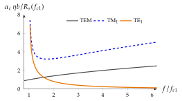
The TE loss falls because the only tangential magnetic field on its plates is , which shrinks as : the zig-zag waves graze the plates and induce less and less current. TEM and TM modes always have their full transverse tangential to the plates. Above TE loses less in the plates than even the TEM wave (Home exercise 7.2.4, Exercise 7.2.5).
Taking the conductor loss of only one plate. The current flows on both plates, equal and opposite, and both dissipate. For TEM this is the difference between and half of it.
Far above cutoff, which mode of a parallel-plate guide has the lowest conductor loss, and how does it scale with frequency?
TE: . TEM and TM grow as .
The coax problem. A coaxial cable carries its current on a thin inner conductor, where is large, so its conductor loss is high, and its dielectric adds . A bigger coax would lose less, but its first higher mode (TE, with , Section 7.5) then moves below the operating frequency. At the coax must stay small: a PTFE semirigid cable (, ) loses .
The hollow guide. A hollow guide has no inner conductor, no dielectric, wide walls, and for TE-type modes a wall current that decreases with frequency above cutoff (Figure 7.2.12). WR-90 (, Section 7.3) loses at and, with the air breakdown field of (Section 3.4.4), carries about peak.
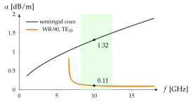
The price is that a waveguide works only in a band (WR-90: to , between and the next mode), it is rigid and bulky, and it is dispersive (Application 7.1.1 in Section 7.1). Below about a guide would be too large, and coax wins. Radar feeds, satellite earth stations, high-power transmitters and accelerators use waveguide (Worked example 7.2.2).