Section 3.4 · Topic 4 of 12
3.4.4 Dielectric strength
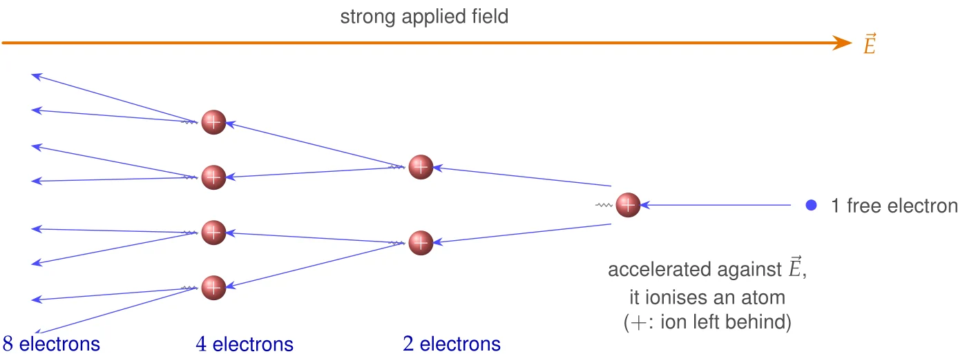
A dielectric cannot withstand an arbitrarily strong field. If the electric field is very strong, the few free electrons that every material contains are accelerated so violently between collisions that they knock further electrons out of the atoms they hit. These are accelerated in turn, and an avalanche of charge carriers develops (Figure 3.4.8). The material becomes conducting, large currents may flow, and in a solid a permanent conducting channel is usually burnt into the material. This phenomenon is called dielectric breakdown. A spark in air and the puncture of a capacitor are both examples.
The maximum electric field intensity that a dielectric material can withstand without breakdown is called its dielectric strength, [V/m].
Typical textbook values are given in Table 3.4.2. Measured values depend on the thickness of the sample, its purity, the temperature and the waveform of the applied voltage, so the table also shows the range of values usually reported.
Table 3.4.2. Dielectric strengths of some materials: typical textbook values and the approximate range reported in practice.
| Material | Dielectric strength | Reported range (approximate) |
|---|---|---|
| Air (1 atm) | MV/m | MV/m for mm–cm gaps |
| Mineral oil | MV/m | – MV/m |
| Rubber | MV/m | – MV/m (neoprene) |
| Glass | MV/m | – MV/m (window glass), – MV/m (borosilicate) |
| Mica | MV/m | – MV/m |
Two practical consequences follow at once. First, the field, not the voltage, decides whether an insulation survives: kV across a cm gap of air ( MV/m on average) is just at the limit, the same kV across mm certainly produces a spark, while V across mm is perfectly safe. Second, the insulation fails where the field is largest, which is why the field maximum, not its average, is the quantity a designer must compute. Both points will return in the applications and in Worked examples 3.4.1 and 3.4.2.
Two flat electrodes are mm apart in air. Roughly what is the highest voltage they can hold? And if the gap is filled with mica?
In air MV/m gives kV. With mica ( MV/m) the limit rises to about kV. In practice it is far less, because the edges of real electrodes concentrate the field, but the factor shows why solid insulation is used.
Two applications at a glance
The ideas of this section are at work in a great many devices. We pick two that use them directly. The relative permittivity and the dielectric strength decide how much energy a capacitor stores (Application 3.4.1), and the relation together with the energy density explains how defibrillators and supercapacitors store and deliver energy (Application 3.4.2). Figure 3.4.9 gives an overview. Each application is placed in the text right after the topic it uses. The two worked examples at the end of the section (Section 3.4.12) are tied to these applications.


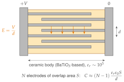
A capacitor is two conductors separated by a dielectric, and the dielectric does two jobs at once. For the parallel-plate geometry we shall derive (Section 3.4.10 and Problem 3.4.1) , while the field between the plates is and may not exceed the dielectric strength. Hence
where is the energy stored per unit volume of the field, to be derived in Section 3.4.9. A large capacitance in a small volume calls for a large , a thin dielectric and a large plate area. A high voltage rating calls for a large dielectric strength, and the largest energy that one cubic metre of dielectric can store is set by , that is, mainly by the dielectric strength. Three technologies show the trade-offs.
- Ceramic capacitors (class 2, BaTiO-based). The ferroelectric ceramic has , but it is strongly nonlinear: falls with increasing field and changes with temperature. In the multilayer construction of Figure 3.4.10, interleaved electrodes of overlap area enclose dielectric layers in parallel, so . Values from nanofarads up to about μF are made in millimetre-size parts.
- Film capacitors (polypropylene). Here only, but a film – μm thick withstands about MV/m and is operated at up to a few hundred MV/m. The film is linear and has very low loss. It is also self-healing: the electrodes are metal layers evaporated onto the film, only some tens of nanometres thick, and a local breakdown vaporises the metal around the fault, which isolates it instead of short-circuiting the capacitor. Film capacitors are the choice for pulse power and AC applications.
- Aluminium electrolytic capacitors. The dielectric is a layer of aluminium oxide, AlO (), grown electrochemically on the aluminium foil, and only about nm of oxide is needed per volt of rated voltage. Because the foil is etched to a very rough surface, is huge while is tiny, and capacitances of millifarads result. The price: the capacitor is polarised (it must not be reverse-biased) and lossy.
Air at its breakdown field of MV/m stores J/m. Polypropylene at MV/m stores J/m J/cm, about times more. Of this factor, contributes only , while the remaining comes from .
A dielectric that does not fill the gap completely can even be harmful. If a mica slab fills half the gap of an air capacitor, the slab and the remaining air layer act as two capacitors in series. The normal component of is continuous across the mica surface (Section 3.4.6), so the field in the air is times the field in the mica, and the air breaks down first. As Worked example 3.4.1 shows, the capacitor with half a gap of mica withstands only kV, against kV for the empty gap: a dielectric that does not fill the gap lowers the voltage rating.