Section 3.4 · Topic 10 of 12
3.4.10 Capacitance
The concept of capacitance
Consider an isolated conductor carrying the total charge . Its potential (with respect to infinity) is determined by the field that produces. If we double the charge, the surface charge density doubles at every point (the distribution cannot change, because the doubled distribution still makes the conductor an equipotential and, by the uniqueness theorem, is therefore the solution), so the field doubles everywhere, and so does the potential. The potential of an isolated conductor is thus directly proportional to the total charge on it:
The constant of proportionality is called the capacitance of the isolated conductor.
The same argument applies to the more important case of two conductors carrying equal and opposite charges and , such as the plates of a capacitor. Then is the potential difference between them.
The capacitance of an isolated conductor, or of two conductors carrying , is
where is the potential of the conductor (with respect to infinity), or the potential difference between the two conductors (from the positive to the negative one).
The capacitance does not depend on or separately: it is determined by the geometry of the conductors and by the permittivity of the medium between them. Think of a water tank: its cross-section (the capacitance) decides how much the level (the voltage) rises for each litre (charge) poured in, but the cross-section does not depend on how much water is inside. This suggests a general recipe (Figure 3.4.25).
- Charge: put on one conductor and on the other (or per unit length).
- Field: find from Gauss's law (Section 3.2), using only the free charge, and then with the local permittivity.
- Voltage: integrate from the negative to the positive conductor (Section 3.3), layer by layer if the dielectric is layered.
- Divide: . must cancel, and if it does not, there is an error.
Alternatively, solve Laplace's equation for with the two conductor potentials as boundary conditions, and obtain from (Problem 3.4.1).

"If I double the voltage, the capacitance halves." This is wrong. Doubling doubles , and the ratio is fixed by the shape and size of the conductors and by alone. In particular, of an uncharged capacitor is not zero.
The three classical geometries

Parallel-plate capacitor
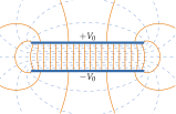
Let the plates of area carry and neglect the fringing field at the edges (valid when the plate dimensions are much larger than , and Figure 3.4.27a shows what we neglect). The charge spreads uniformly with on the inner faces. By the conductor boundary condition (or a pillbox, Section 3.2), between the plates, directed from the positive to the negative plate, so . The field is uniform, and the voltage is . Hence
Coaxial capacitor
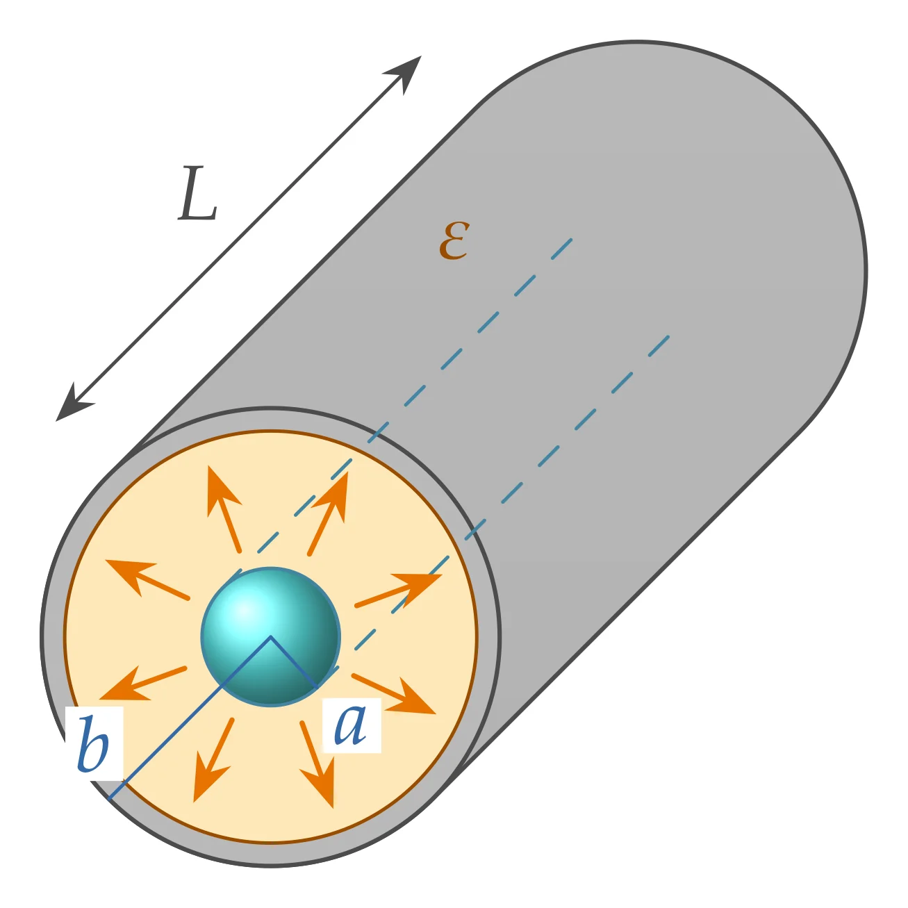
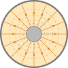
Let the inner cylinder carry and the outer , i.e. per unit length, and neglect end effects (). Gauss's law on a coaxial cylinder of radius () and length gives , so
Eliminating between and gives the field in terms of the voltage,
which is largest at the surface of the inner conductor. This maximum field decides the voltage rating of a cable, .
Try the coaxial geometry in the designer below: set and to obtain about pF/m, and see how slowly changes with the radius ratio and where the field is largest.
Spherical capacitor
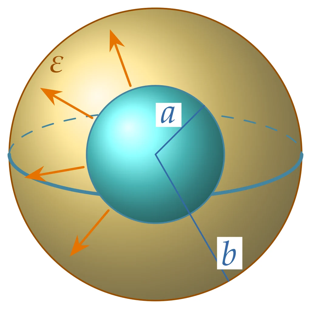
Let the inner sphere carry and the outer . Gauss's law on a concentric sphere of radius () gives , so
The limit is the capacitance of an isolated sphere of radius .
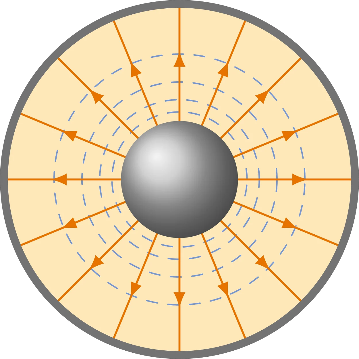
Checking the limits
When the gap is small compared with the radius, , both curved capacitors must look like parallel plates. For the coaxial capacitor , so with . For the spherical capacitor , so with .
How large is a farad?
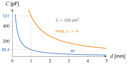
An isolated sphere in air has : pF per centimetre of radius. Even the whole Earth ( km) has only μF. One farad is a very large capacitance, which is why practical values are quoted in pF, nF and μF, and why the F of a supercapacitor (Application 3.4.2) is so remarkable. Figure 3.4.28 gives a feel for parallel plates: cm plates mm apart in air have pF, and a mica filling raises this six-fold.
Try the parallel-plate geometry in the designer below: change the plate area, the gap and and compare the capacitance with , then raise the voltage until the field reaches the dielectric strength.
Layers in series, strips in parallel
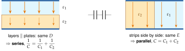
Real capacitors often contain more than one dielectric. Two simple arrangements cover most cases (Figure 3.4.29). If the layers are parallel to the plates, every layer carries the same (normal component continuous) and the voltages of the layers add: the capacitor behaves as capacitors in series. If the dielectrics sit side by side, each strip sees the same voltage and the same (tangential component continuous across the interface) and the charges add: capacitors in parallel. Home exercise 3.4.1 derives the two combination rules, and Worked example 3.4.1 and Home exercise 3.4.4 use them.
(a) A capacitor holds nC at V. What is its capacitance at V? (b) A slab of glass covers the left half of the plate area of an air capacitor and fills the gap from plate to plate. Series or parallel?
(a) pF at any voltage, and at V it holds nC. (b) Parallel: the glass and the air strips are side by side between the same plates.