Section 7.3 · Topic 1 of 11
7.3.1 The guide and the tools of Section 7.1
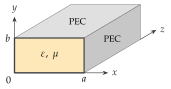
The guide occupies , (Figure 7.3.1). By convention the side is the longer one, . The walls are perfect electric conductors (PEC) and the filling is a lossless simple medium with and , usually air. The wave travels along , so every field component carries the factor (and the time factor , suppressed as always):
As in Sections 7.1 and 7.2, is the phase constant of the wave along the guide, the quantity called for the plane waves of Chapter 6. With the propagation constant is . Below cutoff becomes imaginary, , and decays. Written as a complex wavenumber , the form used for lossy media in Section 6.2, this is the case . The wavenumber of the filling is , its velocity , its wavelength and its intrinsic impedance .
Section 7.1 showed that in a uniform guide the four transverse components follow from the two longitudinal ones by differentiation. With
they read
and , themselves obey the Helmholtz equation . Two families of solutions are possible in a hollow guide. In a TM wave and , in a TE wave and . A TEM wave () would need and a transverse field that is a static field in the cross-section, which a single closed conductor cannot support.
Every mode has its own value of , fixed by the walls. Once is known, the general results of Section 7.1 apply unchanged:
with the guide wavelength , the phase velocity and the group velocity ,
Below cutoff the mode is evanescent, with and
The whole task of this section is therefore to find for every mode of the rectangular guide, and its field pattern.