Section 7.3 · Topic 8 of 11
7.3.8 Applications
The TE mode carries almost all high-power microwave energy that does not travel through free space. Three applications use the results of this section: the size, power rating and loss of a feed line, the wall currents that let a guide radiate through slots, and the single-mode guide that couples a magnetron to an oven.
A radar transmitter, with up to megawatts of peak power, feeds its antenna through a rigid waveguide run with bends, a rotary joint and a feed horn (Figure 7.3.11). Satellite earth stations do the same with the uplink amplifier. A coaxial cable of comparable size would break down at a fraction of the power and lose far more, because its small inner conductor carries the whole current in a thin skin. The two numbers that matter follow from Eqs. (7.3.37) and (7.3.42):
with the breakdown field of dry air. Table 7.3.2 gives typical values for air-filled copper guides.
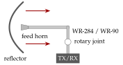
Table 7.3.2. Typical TE feed lines (air, copper, ).
| S-band radar | X-band radar | Ku uplink | |
|---|---|---|---|
| guide | WR-284 | WR-90 | WR-75 () |
- Air-traffic-control radars, with about of peak power, need the large S-band guide. Higher bands handle less power, because the cross-section scales as .
- Guides are kept dry and slightly pressurised: humidity lowers , pressure raises it.
- The feed run also sets the noise of the system. A loss in front of a receiver at the physical temperature adds the noise temperature , so () adds about . Worked example 7.3.1 puts numbers on a complete S-band feed.
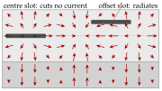
The slotted line. A narrow slot on the centre line of the broad wall cuts no current (Figure 7.3.7) and hardly disturbs the TE field. A probe sliding in it samples along . In front of a mismatched load the incident and reflected waves form a standing wave whose adjacent minima are apart and whose depth gives the standing-wave ratio. This was the classic way to measure , and with it the frequency and the load impedance (Home exercise 7.3.2).
The slotted array. A longitudinal slot offset by from the centre line cuts the crosswise current , which has opposite signs on the two sides of the centre line: it radiates, more strongly for a larger offset (Figure 7.3.12a). Slots spaced apart see the guide wave apart in phase, and putting them on alternate sides of the centre line adds another . All slots then radiate in phase and the beam is normal to the wall (Figure 7.3.12b):
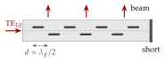
For WR-90 at , and . A array holds slots and gives, with uniform excitation, a beam about wide. Ship, coastal and weather radars use such arrays: they are rugged, have low loss and need no feed network. Away from , and the beam tilts (Worked example 7.3.2).
Adjacent minima of a standing wave are apart, not , because repeats every half wavelength. Taking their distance as gives a guide wavelength shorter than the free-space wavelength, which is impossible for a waveguide mode since .
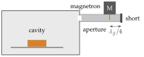
The magnetron of a domestic oven delivers about at . It ends in a short antenna that sticks into a rectangular guide like a probe, parallel to the of TE (Figure 7.3.13). One end of the guide is shorted, the other opens into the cavity through an aperture.
- The short is a node of . A probe in front of it sits at a maximum of the standing wave, where the wave reflected by the short adds in phase to the wave sent towards the cavity.
- A guide of about WR-340 size () is single-mode at : and .
The guide wavelength and the probe position are
Typical numbers:
- in TE: and , far below breakdown.
- The wall loss is about : under is lost in a feed.
- Behind the aperture the cavity is a resonator with many modes (Section 7.8). A stirrer or a turntable evens out the heating.
- The door screen and the vents are waveguides far below cutoff: they give tens of dB of decay in a few millimetres (Home exercise 7.3.1).
Worked example 7.3.3 goes through the design.
Table 7.3.3. The applications of this section.
| Application | Physics used | Worked out in |
|---|---|---|
| Radar and satellite feeds | , of TE | Worked example 7.3.1, Problem 7.3.4 |
| Slotted line and slotted arrays | wall currents , | Worked example 7.3.2, Home exercise 7.3.2 |
| The microwave oven feed | single-mode band, , evanescent modes | Worked example 7.3.3, Home exercise 7.3.1 |