Section 6.3 · Topic 1 of 8
6.3.1 Normal incidence on a plane interface
Let medium 1 () fill the half space and medium 2 () the half space , and let a uniform plane wave, linearly polarised along , travel in medium 1 towards (Figure 6.3.1b). The incidence is normal: the direction of travel is perpendicular to the interface. We take both media lossless first, so that the waves are described by the phase constants and the intrinsic impedances of Section 6.1,
which some texts write as and .
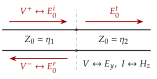
Three waves are needed. The incident wave is given. A reflected wave travels back into medium 1 and a transmitted wave travels on into medium 2. Why should these be plane waves of the same frequency, travelling along ? The boundary conditions must hold at every instant and at every point of the interface. The incident fields there oscillate as and do not depend on or , so the other two waves must do the same: same , no dependence on and , which means travel along . With the phasor convention (time factor suppressed) the three waves are
The amplitude is known, and are the two unknowns. Each magnetic field follows from its electric field by the rule of Section 6.1 for a uniform plane wave travelling along the unit vector ,
For the incident and the transmitted waves and . For the reflected wave , and : hence the minus sign in Eq. (6.3.3). Equivalently, points along the direction of travel, and .
Writing because "". The magnitude is right, but the reflected wave would then carry power towards the interface, and the boundary conditions give , the wrong sign. Always build from Eq. (6.3.5) with the direction of travel of that wave.
The boundary conditions
The general boundary conditions at an interface are those of the static chapters, (Section 3.4.6) and with the unit normal pointing from medium 2 into medium 1 (Section 4.2.3 writes it as ), and they remain valid for time-varying fields (see the box below). A surface current needs an infinite conductivity. For two media of finite conductivity and the tangential is continuous as well. At normal incidence both and are entirely tangential, so these two conditions are all there is. Applied at , they read
Take a thin rectangle straddling the interface, of length along it and height across it, and apply Faraday's law in integral form (Section 5.3), . As the two short sides contribute nothing and the flux through the rectangle, at most , vanishes because is finite. What is left is . The same rectangle in the generalised Ampère law gives : the displacement current through the vanishing area goes to zero with , and so does the conduction current unless a finite current flows in a layer of zero thickness, which needs . The time derivatives therefore change nothing at an interface.
Divide both equations by and introduce the ratios of the amplitudes.
At normal incidence on a plane interface the reflection coefficient and the transmission coefficient are the ratios of the electric-field amplitudes at the interface,
also written and in some texts (in this book and denote the power fractions).
The boundary conditions Eq. (6.3.6) and Eq. (6.3.7) become two linear equations,
Adding them eliminates : , so , and then .
A uniform plane wave incident normally from medium 1 on medium 2 is reflected and transmitted with
Only the impedances matter. If medium 2 has the same intrinsic impedance as medium 1 the wave does not notice the interface (, ), however different the speeds are. The larger the impedance step, the stronger the echo, and its sign tells which medium has the larger impedance.
The transmission-line picture
Equations (6.3.9) are exactly those of two transmission lines joined end to end (Figure 6.3.2a). With the correspondence , and , the interface is the junction, the incident and reflected waves are the forward and backward voltage waves and on line 1, and medium 2, carrying only a forward wave, acts on line 1 as a load . The reflection coefficient Eq. (6.3.10) is the familiar . The analogy will pay off with two interfaces, where it turns a four-equation problem into one line of algebra.
Lossy media
Nothing in the derivation used the reality of . If a medium is lossy, its intrinsic impedance and its propagation constant are complex (Section 6.2),
the transmitted wave becomes , and Eq. (6.3.10) holds unchanged with complex and . Some texts write the same wave as with the complex wave number , so that . The two notations describe the same field.
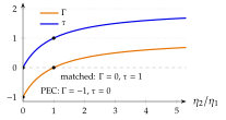
When medium 2 is a perfect electric conductor (PEC), and
nothing enters the conductor and the reflected field cancels the incident one on its surface.
Reading the formulas
For lossless media . when medium 2 has the lower impedance, which for nonmagnetic dielectrics is the denser medium (larger ). The transmitted field then has the opposite sign to the reflected one, and . When medium 2 has the larger impedance, and exceeds (Figure 6.3.2b): the transmitted field is larger than the incident one. A larger field is not a larger power, as the next subsection shows.
A plane wave in air falls normally on still water, treated here as a lossless dielectric with , . Find and .
, so and . The reflected field is of the incident one and inverted. (Real water is lossy at most frequencies, which changes but not the method.)