Section 6.4 · Topic 5 of 13
6.4.5 Where the power goes
At normal incidence the fraction of the incident power that is reflected is and the fraction that is transmitted is (Section 6.3). At oblique incidence a factor appears that has to do with geometry, not with the waves. Consider a patch of area on the interface, lit by a beam (Figure 6.4.5). The incident beam that covers the patch has the cross-section , the reflected beam the same, and the transmitted beam the cross-section . Each beam carries the time-average power density through its own cross-section. The power balance must be written for the power that crosses the patch, that is for the normal components of the Poynting vectors:
for either polarisation, with or . They are also called the reflectivity and the transmissivity of the interface.
Whatever is not reflected is transmitted. The reflected fraction is simply , because the reflected beam is a mirror image of the incident one. The transmitted fraction carries the extra factor , because the transmitted beam has a different width.
That is not an extra assumption: it follows from the boundary conditions. For S polarisation multiply the two equations Eq. (6.4.12): , which is . The tangential and are continuous, so the normal component of , which is built from the tangential components only, is continuous too.
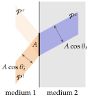
Using the normal-incidence formula at an oblique angle gives . The power densities , , refer to three different cross-sections. Only their normal components , the power per unit area of interface, add up. A quick test of any oblique calculation is to check that .