Section 6.4 · Further exercises · 10 of 10
Exercise 6.4.10: A copper wall at oblique incidence
About the further exercises of Section 6.4
Ten further exercises in the spirit of Problems 6.4.1–6.4.6 and the home exercises, in two groups each graded from easy to harder: Exercises 6.4.1–6.4.5 on the coefficients, the critical angle and the Brewster angle, Exercises 6.4.6–6.4.10 on applications in radio, fibre optics, microscopy, radomes and metal walls. They use only the equations listed at the head of this subsection and, where stated, the normal-incidence results of Section 6.3.
A copper wall at oblique incidence
#A plane wave in air falls at the angle on a flat copper surface (). (a) Find and , and show that for every . (b) Taking , show that the absorbed fractions are and as long as , and evaluate them at , and . (c) Find the exact (still with ), its maximum and the angle where it occurs. (d) Check (b) by the power-loss method: the power absorbed per unit area of a good conductor is , with taken from the perfect-conductor solution.
In a good conductor , so Snell's law forces : the wave enters the metal along the normal at every angle of incidence. With the Fresnel formulas contain (S) and (P), and for with real . For a good conductor with (Section 6.2).
, , . Since and , : .
S: , so . P: , so . With :
With , and
At a perfect conductor the tangential is for S (Problem 6.4.4) and for P (Home exercise 6.4.4), while the incident wave brings per unit area of the wall:
the same as in (b).
The full Fresnel formulas with the complex give at (approximation ) and the same maximum . The maximum does not depend on : every good conductor absorbs of a P wave at the angle where .
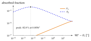
The P wave has a normal and a tangential that stays at even at grazing incidence, while the power it brings per unit area of wall vanishes as : hence grows towards grazing. For copper at the peak lies only from grazing. At optical frequencies, where is much larger (Exercise 6.3.6), it moves to angles of to and is used to characterise metal surfaces. The power-loss method of (d) is exactly how the wall losses of waveguides are computed in Chapter 7.
cf. Problem 6.4.4