Section 6.1 · Topic 6 of 9
6.1.6 Polarisation of plane waves
The polarisation of a uniform plane wave is the time-varying behaviour of its electric field intensity at a given point in space: the curve traced by the tip of during one period.
The magnetic field needs no separate description: is turned rigidly by about , so it traces the same curve, turned, in the same sense. The procedure for finding the polarisation is always the same.
- Determine the electric field of the plane wave, if it is not given: . Read from the exponent: travels towards , towards .
- Express the electric field in the time domain, .
- Choose a point. All space coordinates equal to zero is mathematically convenient.
- Draw the resulting vector for increasing time, , and see which curve its tip follows.
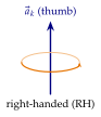
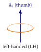
- If the curve is a circle or an ellipse, use the right or left hand to decide the sense of rotation, with the thumb along the direction of propagation.
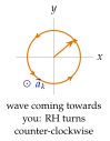
Point the thumb of the right hand along . If the fingers curl the way turns in time, the wave is right-handed (RH). Otherwise it is left-handed (LH). For an observer facing the oncoming wave, an RH wave turns counter-clockwise. This is the convention of IEEE Std 145 and of this book. Many optics books use the opposite name for the same wave, so the convention must always be stated.
The general case: the polarisation ellipse
Any uniform plane wave travelling towards is the sum of an - and a -polarised wave. Choosing the time origin so that the component has zero phase,
whose components in the time domain are
To find the curve, eliminate the time. With , and , so . Squaring and replacing by ,
the equation of an ellipse inscribed in the rectangle , . Two special cases stand out, and every other case is elliptical:
- linear polarisation: or , or one of , zero. The ellipse collapses to a line segment,
- circular polarisation: and . The ellipse becomes a circle,
- elliptical polarisation: every other case.
The hand follows from the sign of . For the component lags the component, so turns from towards , a right-handed rotation about :
Figure 6.1.14 shows the traces for equal amplitudes and eight values of .
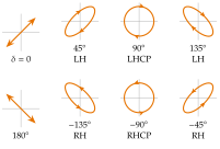
Sweep below, or tap a thumbnail, and watch the trace go from a line at through a right-handed ellipse for and back to a line at . The tool starts on the left-handed ellipse of Figure 6.1.16. Set and the trace becomes a circle at , as in Figure 6.1.14.
Circular polarisation in time and in space
Take , that is and . With ,
At the field turns from () to () at constant length . With the thumb along the fingers follow: the wave is right-hand circularly polarised, RHCP. At , on the other hand, : the tips of the field vectors along the -axis form a helix that winds the other way, a left-handed screw (Figure 6.1.15). As grows the whole helix slides along at , and at any fixed point the field vector it carries past turns in the right-handed sense.
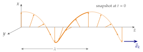
The polarisation is defined by the rotation in time at a fixed point, never by the shape of the field in space at a fixed time. The frozen spatial pattern of an RH wave is a left-handed helix. Judge the hand from , as in the recipe.
Elliptical polarisation: axial ratio and tilt
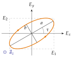
The ellipse of Eq. (6.1.55) has the semi-axes and the tilt angle of its major axis from the -axis given by
The shape is summarised by the axial ratio
equal to for circular and infinite for linear polarisation. Data sheets quote it in decibels, . For , , (Figure 6.1.16) the formulas give , , () and , and since the wave is left-handed. The quadrant of is chosen so that the major axis lies in the quadrants where has the sign of . With the denominator vanishes and .
Any polarisation is a sum of two circular waves
The two circular waves along , (RH) and (LH), form a basis just as and do. Writing
and comparing components, and .
The larger of , sets the hand. Equal circular parts give a line, one of them zero gives a circle.
An ellipse is what a big circle and a small counter-rotating circle trace together. Where the two rotating phasors line up the field is longest, , where they oppose it is shortest, . The power splits between the two circles as .
The last relation of Eq. (6.1.61) follows from : the two circular waves carry power independently.
A quick test for the hand
The recipe can be shortened to a single cross product. Write the complex amplitude at the reference point as with real vectors , . Then gives and, at a quarter period, . The field turns from towards .
- Write the complex amplitude as and read from the exponent.
- If the polarisation is linear.
- Otherwise the wave is RH if and LH if it is .
- It is circular if, in addition, and .
The test works for too, since turns rigidly with , and for any direction , not only along the axes.
For along : , , and : RH, as found above.
Classify and .
The first: , , , equal and perpendicular: LHCP, travelling towards . The second has no imaginary part: linear, along , travelling towards .
What fraction of the power of the wave is left-hand circular?
gives and , so (Problem 6.1.3).
Applications: uniform plane waves and polarisation
Far from a transmitter every wave is a uniform plane wave: , , . What a receiver gets out of it depends on one more thing, the polarisation of the wave compared with that of the receiving antenna. If both are described by unit polarisation vectors written for the same direction of propagation, for the wave and for the antenna, the fraction of the available power that the antenna collects is
Three everyday systems are built around it.
The problem. A satellite does not know how the receiver is held, and the ionosphere turns the plane of a linearly polarised wave by an amount that varies with the time of day and falls as , of the order of at (ITU-R P.531). This Faraday rotation can leave a linear receiving antenna crossed with the wave. Exercise 6.1.10 shows how it arises from the two circular components of a linear wave.
The cure. Rotating a circle changes nothing. All GPS signals are RHCP (L1 at , L2 at , L5 at ), and so are most mobile-satellite links. Table 6.1.1 lists what antennas of different polarisations receive from an RHCP wave.
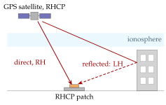
Bonus: multipath. A reflection from metal or wet ground reverses the hand (Home exercise 6.1.4). An RHCP antenna therefore rejects the strongest echoes, the ones that spoil the range measurement of a navigation receiver (Figure 6.1.17). A good GPS patch antenna has an axial ratio below towards the zenith. It grows towards the horizon, where the antenna becomes more nearly linear and the rejection of the opposite hand weakens (Exercise 6.1.9).
Table 6.1.1. Polarisation match of a wave and an antenna.
| wave antenna | in dB | |
|---|---|---|
| RHCP RHCP | ||
| RHCP any linear | ||
| RHCP LHCP | (real antennas: to ) | |
| linear linear at the angle |
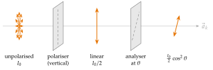
The polariser. A dichroic sheet, stretched polyvinyl alcohol stained with iodine, absorbs the component of along its long-chain molecules and passes the perpendicular one, the transmission axis. A linear wave at the angle to the transmission axis keeps the field , so the intensity, proportional to , obeys
Unpolarised light (natural light, whose and direction change randomly and fast) loses exactly half, whatever the orientation of the sheet. Real sheets pass about of it.
Sunglasses. Light reflected from water, wet roads or a car bonnet near the Brewster angle ( for water, Section 6.4) is mostly horizontally polarised. Polarised sunglasses have a vertical transmission axis: the glare is blocked and the diffuse light is halved.
The LCD pixel. A twisted-nematic cell sits between crossed polarisers. With no voltage its molecules form a helix that turns the polarisation by , and the light passes the front polariser (white). A few volts align the molecules with the field, the turning stops and the front polariser blocks the light (black). Each pixel is a voltage-controlled polarisation rotator (Worked example 6.1.2, Home exercise 6.1.3). Turn polarised sunglasses in front of a laptop screen: at one angle the screen goes dark, because its front polariser acts as the analyser.
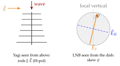
Match the field. A wire element responds only to the component of along it: the induced voltage goes as and the power as (Table 6.1.2). Terrestrial TV transmitters radiate horizontal or vertical linear polarisation, and the rods of a rooftop Yagi antenna must be parallel to : horizontal for an H-polarised transmitter, turned through for a V-polarised relay. Two transmitters on the same channel are often given opposite polarisations. The to that a turned aerial loses, its cross-polar discrimination, is part of the frequency plan.
Satellite TV. Ku-band broadcasting ( to ) sends two independent programmes on the same frequency, one V-polarised and one H-polarised. The LNB (low-noise block converter) at the focus of the dish has two orthogonal probes, and the receiver picks one with the supply voltage ( for V, for H) and the band with a tone. The satellite's "vertical" is parallel to the Earth's axis. From a site at latitude , at the longitude difference from the satellite, it looks tilted by the skew angle
and the LNB must be turned by (Figure 6.1.19, Worked example 6.1.3).
Table 6.1.2. Co-polar loss of a linear antenna misaligned by .
| misalignment | loss (dB) |
|---|---|
Signal strength forgives misalignment, because a cosine is flat near zero: costs . Interference does not, because a sine is steep near zero: the same lets the other polarisation leak in only down, which ruins a frequency plan that relies on of isolation.