Section 6.2 · Topic 4 of 9
6.2.4 Low-loss dielectrics and good conductors
The loss tangent
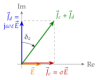
When a medium has some conductivity, the ratio decides how it behaves. It has a direct meaning in Ampère's law Eq. (6.2.1): it compares the two currents on the right-hand side, the conduction current and the displacement current . In the complex plane (Figure 6.2.4a) the two are perpendicular, in phase with and leading it by , and the angle by which their sum is tilted away from is the loss angle.
A medium with is a low-loss dielectric, a medium with a good conductor. In practice is taken as low-loss and as a good conductor. A dielectric with polarisation loss, , has .
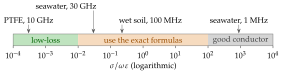
The loss tangent is a property of the medium at a frequency. Since falls as for a constant , every conductor becomes a dielectric at a high enough frequency and every lossy dielectric a conductor at a low enough one. The crossover lies at the frequency
for seawater, for moist sandy soil (Exercise 6.2.1) and far above any radio frequency for a metal. Figure 6.2.4b places some common cases.
Perfect dielectrics
For a dielectric material the conductivity is zero and the relative permeability one: , , . Then is real, so that
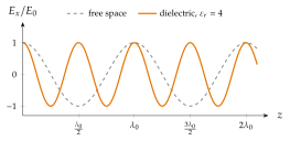
Waves propagating in a dielectric do not decay. At the same frequency the wave is slowed and shortened by the refractive index , (Figure 6.2.5), and for the same the magnetic field is times larger than in air.
Low-loss dielectrics: the approximate formulas
Write Eq. (6.2.6) as with , and expand with the binomial series for :
In the same way in Eq. (6.2.12).
A little conductivity hardly changes the wave: its speed, wavelength and impedance are those of the lossless dielectric to within . It only adds a slow decay, with an that does not depend on the frequency when is constant.
When the loss is a polarisation loss, , the attenuation constant grows in proportion to , . A useful rule of thumb follows from and :
A cable with PTFE insulation () therefore loses only per wavelength in its dielectric. Most of its loss is in the copper, through the skin effect of the next subsection. Table 6.2.1 collects typical values.
Table 6.2.1. Relative permittivity and loss tangent of some dielectrics.
| Material | Where used | ||
|---|---|---|---|
| PTFE (Teflon), 10 GHz | microwave substrates, coaxial cables | ||
| Polyethylene, 10 GHz | cable insulation | ||
| Alumina, 10 GHz | thin-film circuits | ||
| FR-4 (PCB), 1 GHz | ordinary printed circuit boards | ||
| Water, 2.45 GHz | the microwave oven (Worked example 6.2.1) | ||
| Seawater, 30 GHz |
With the model , of Problem 6.2.1.
Good conductors
For the displacement current is negligible against the conduction current, and Eq. (6.2.6) becomes
since . The real and the imaginary parts are equal. Their common value defines the skin depth.
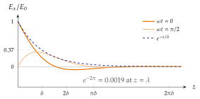
Inside a good conductor the wave dies within one wavelength. Its field falls to in one skin depth , its wavelength is only , and its impedance is tiny with a phase of exactly .
Figure 6.2.6 shows how fast this is: at only of the field is left. The impedance is small and inductive. Copper () at has against in air, so in a metal is large and almost vanishes. That is why a metal surface looks like a short circuit to an incoming wave (Section 6.3).
Taking or inside a conductor. Inside a good conductor , which has nothing to do with : seawater at has against in air (Application 6.2.1). The electrical size of an antenna submerged in the sea is measured with this wavelength.
Seawater (, ) at : which class, and what is the skin depth?
: a good conductor, and .