Section 6.2 · Topic 6 of 9
6.2.6 Plasmas and the ionosphere
The ionosphere
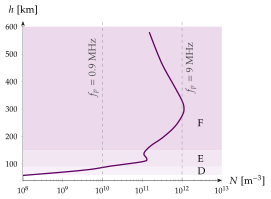
The region of the earth's atmosphere from roughly to altitude is called the ionosphere. The gas at these heights is so thin that ultraviolet radiation from the sun can detach electrons from neutral atoms and molecules when it is absorbed, and the electrons recombine only slowly. The ionosphere therefore contains free electrons and positive ions. These charged particles are also bound by the earth's magnetic field, and they affect the propagation of radio waves. Their density changes with the sunspot cycle, with the season and with the hour of the day. An ionised gas with equal densities of electrons and positive charge is called a plasma. Figure 6.2.9 shows a typical daytime profile with its layers, D (about to ), E ( to ) and F (above ). At night the D layer disappears and the F layer weakens.
The motion of a free electron
Consider a free electron, of charge and mass , in the electric field of a time-harmonic wave. From Coulomb's law and Newton's second law of motion,
where is its displacement from the rest position. In time-harmonic form, , this becomes , which yields
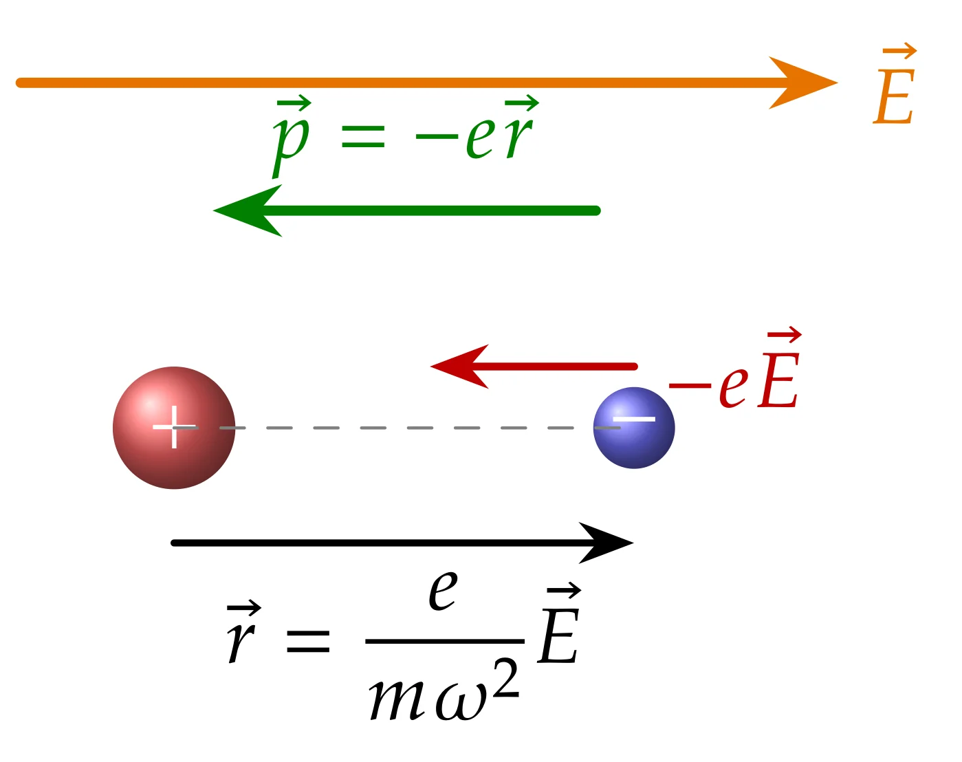
The ions are at least times heavier and are taken at rest. Collisions with neutral molecules and the earth's magnetic field are neglected, so the plasma is lossless and isotropic. The constants are and . The displacement of the electron from its ion gives rise to an electric dipole moment
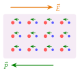
The force on the electron points against , yet the displacement of Eq. (6.2.33) points along : an oscillating mass is always out of phase with the force that drives it (Figure 6.2.10a). The dipole moment therefore points against the field, the opposite of what happens in an ordinary dielectric (Section 3.4).
Polarisation, plasma frequency and the equivalent permittivity
If there are electrons per unit volume, the polarisation vector is
and the electric flux density becomes
Writing this as defines the plasma angular frequency and the plasma frequency.
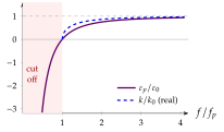
A plasma is a medium with a permittivity smaller than that of vacuum, and the smaller the lower the frequency. Below the permittivity is negative and no wave can propagate: is the cutoff frequency of the plasma.
The numerical form of follows with , and . The polarisation of Eq. (6.2.35) points against , so the susceptibility is negative: a plasma is "less than vacuum". The plasma frequency is also the natural frequency at which the electron cloud oscillates about the ions when it is displaced and released. At the permittivity vanishes, and while : this is the plasma oscillation.
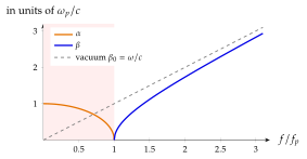
The wave number in the plasma follows from as in Eq. (6.2.38). Two regimes appear (Figure 6.2.11a):
- for , is purely imaginary, so there is no propagation,
- for , is purely real, so there is no attenuation.
The electron density of the ionosphere ranges from about in the lowest layer to in the highest, which gives plasma frequencies from to (Figure 6.2.11b). For communication through the ionosphere, with a satellite, the frequency of the wave must therefore be well above . Since , a hundredfold denser plasma has only a tenfold higher cutoff. Satellite links (GPS at , television at ) are far above every ionospheric , but the plasma around a re-entering spacecraft is not (Problem 6.2.2).
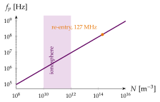
Below the plasma frequency: evanescence and total reflection
With the two regimes read
Below cutoff the field does not oscillate in space at all: it only decays, which is called an evanescent field (Figure 6.2.12). Its impedance is purely imaginary. The root of must be taken as , so that is positive and the field decays towards , and then
The last form is Eq. (6.2.13), , with . Electric and magnetic fields are in quadrature and no power flows on average. The field decays, but nothing is absorbed, since there are no collisions: the energy must go back. A wave meeting a plasma with is therefore totally reflected.
A wave of frequency incident vertically on a layer whose electron density grows with height turns back at the height where , that is where
The highest frequency returned at vertical incidence is the critical frequency of the layer.
A plasma acts as a mirror for every frequency below its plasma frequency and as a window, slightly slower in its group velocity, for every frequency above it.
Sweeping the frequency upwards at vertical incidence and timing the echoes maps the profile : each frequency turns back at its own height, Eq. (6.2.42), and the highest frequency still returned is the critical frequency . This is how profiles like Figure 6.2.9 are measured. Strictly, the echo time gives the group delay, the subject of Section 6.2.7.
The F layer has . Is a wave sent straight up returned, and at which electron density?
, so the wave is returned, at the height where , on the lower side of the layer.
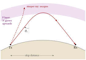
A short-wave (HF, to ) signal sent obliquely upwards is turned back by the ionosphere and lands hundreds or thousands of kilometres away. One hop via the F layer covers up to about , and several hops go round the world. Short-wave broadcasting, amateur radio, aircraft and ship communication and over-the-horizon radar all use this path.
To see why oblique rays return frequencies that pierce the layer overhead, slice the layer into thin horizontal slabs. In each slab the refractive index is
which decreases upwards as grows. Snell's law of refraction (Section 6.4), applied from slab to slab, keeps the product constant:
with the angle of incidence at the bottom of the layer, where . As decreases the ray bends away from the vertical, and it turns back where it becomes horizontal, , that is where :
At the peak of the layer this gives the highest frequency that is still returned.
the maximum usable frequency for a ray incident on the layer at the angle from the vertical.
With a peak density the critical frequency is , and at
Higher frequencies, or steeper rays, escape into space. This is why satellite links use VHF and higher frequencies, and why a skip zone surrounds the transmitter (Figure 6.2.13): near the transmitter the rays are steep, is small, and a frequency above is not returned until is large enough.
By day the D layer absorbs the low HF frequencies through electron collisions, the loss we neglected (Exercise 6.2.13 shows that a sky wave loses about in it). At night the D layer vanishes, drops to a few megahertz, and the lower HF bands open for long distances while the higher ones close. Home exercise 6.2.2 works the secant law with numbers.
Change and below and see which frequencies are returned to earth. With and every frequency below comes back.