Section 7.8 · Topic 13 of 18
7.8.13 The TE₀₁₁ mode and the mode chart
The TE mode is the TE mode of the circular guide with one half guide wavelength between the end plates. With ,
Three properties make it special.
- Its wall currents flow only along : on the side wall with there, and on the end plates with . None of them crosses the joint between the side wall and an end plate, so a sliding non-contacting plate can tune it without spoiling it. This is the mode of wavemeters.
- Its is very high, to for copper in the X band (Worked example 7.8.2).
- It is degenerate with TM, because (from ).
The mode chart
Multiply Eq. (7.8.29) by and square:
where is or . Plotted against , every mode is a straight line, with intercept and slope (Figure 7.8.13, with for air). A vertical line at the of a given cavity lists all its resonances in order, with . A tuning plunger, which changes , moves the cavity along the horizontal axis. The lines (TM, TM) are horizontal, and the point , where TE crosses TM, is the limit of Eq. (7.8.30).
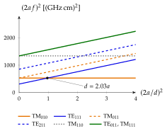
An air-filled pillbox has and . Which mode is the lowest, and at what frequency?
, so TM: . On the chart , where the TM line () lies far below TE ().
A cavity is a resonant circuit in which and are no longer separate elements: fills the middle, the regions near the walls, and the energy moves between them. It has many resonances instead of one, and a about a hundred times higher. As an order of magnitude, , about for copper at .
THE ABSORPTION WAVEMETER
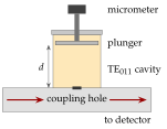
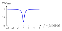
A TE cavity hangs on a guide through a small coupling hole (Figure 7.8.14a). Off resonance it takes no power. At resonance it absorbs a little, and the detector after the guide shows a dip. The plunger is turned until the dip appears, and the frequency is read from the micrometer that sets . The non-contacting plunger does not spoil , because the TE currents do not cross the gap around it, and the degenerate TM mode, whose currents do, has its destroyed and shows no dip:
CAVITY FILTERS
A transmission cavity, with two couplings, passes a band around and reflects the rest. Base stations, satellites and radar receivers chain several of them to obtain steep skirts. The loss at the centre follows from Eq. (7.8.27),
so a narrow band (large ) costs loss unless is much larger still.
| Wavemeter (X band) | Filter () | |
|---|---|---|
| (TE, copper) | ||
| close to (weak coupling) | ||
| Centre loss | a small dip |
A filter with loaded to passes with . No lumped filter could do this: its of about is below the required. Narrow-band filters therefore use cavities, often silver-plated, or low-loss ceramic dielectric resonators. Worked example 7.8.2 designs an X-band wavemeter.
THE TM PILLBOX
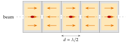
On the axis of a TM cavity the electric field is axial and largest. A bunch of particles moving at that crosses a cell of length in half a period always sees pointing forward and gains energy all the way. Chains of such cells, with the field alternating from cell to cell (the " mode", Figure 7.8.15), form linear accelerators (linacs) for medical radiotherapy, synchrotron light sources and free-electron lasers. A klystron uses the same field to bunch an electron beam in a first cavity and a second cavity to extract microwave power from the bunched beam, and klystrons power most radars and accelerators. Because the field changes while the particle crosses the gap, the energy gain is reduced by the transit-time factor :
A particle entering at the field maximum sees while it moves from to , and the average of this over the cell is . For , .
| Copper, S band | Niobium, | |
|---|---|---|
| Radius | ||
- A copper cell at stores about and loses in its walls (Worked example 7.8.3). Copper linacs are therefore pulsed, with pulses a few microseconds long.
- Superconducting niobium has in the n range, so is about six orders of magnitude higher and the cavities can run continuously. The loaded is then set by the power coupler.