Section 7.8 · Topic 14 of 18
7.8.14 Microwave devices
A cavity is one of many waveguide components. Microwave devices are the components used to generate, guide, control and measure high-frequency signals, usually quoted as to ( from to ). Most waveguide hardware works between and (from WR-650 to WR-10). At these frequencies lumped elements (, , ) become inaccurate as soon as their size approaches the wavelength ( at ): the phase varies along them, they radiate, and their leads add inductance and capacitance. Transmission lines and waveguides are used instead as distributed structures, and the behaviour of a component is described by power waves and scattering parameters.
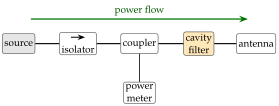
Figure 7.8.16 shows a transmitter chain built from the components of this section. The isolator protects the source from reflections, the coupler samples the power for a meter, and the cavity filter removes out-of-band signals.
Common waveguide components
- Bends, twists and transitions route the power with minimal reflection.
- Irises and posts introduce inductive or capacitive discontinuities, used for matching and as the couplings of cavity filters.
- Directional couplers sample a small fraction of the power travelling in one direction.
- Isolators and circulators protect sources from reflected power.
- Cavity resonators are the high- frequency-selective elements.
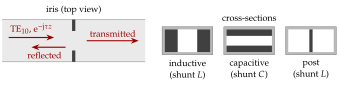
An iris (Figure 7.8.17) excites evanescent higher modes (Section 7.3) that store energy next to it. Vertical strips and posts store mainly magnetic energy and act as a shunt inductance. Strips that narrow the gap between the broad walls store electric energy and act as a shunt capacitance. Two irises apart form a cavity, which is how most waveguide filters are built.
Junctions and non-reciprocal components
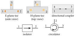
Figure 7.8.18 shows the symbols of the most common multiport components.
- Tees. In an E-plane (series) tee a wave fed into arm 3 leaves arms 1 and 2 in opposite phase. In an H-plane (shunt) tee it leaves them in phase. A junction with both side arms is the magic tee (Exercise 7.8.8).
- Directional coupler. Two guides share a wall with coupling holes. A forward wave in port 1 sends a small sample to port 3 and nothing to port 4 (Section 7.8.16).
- Isolator and circulator. These are non-reciprocal, built with a magnetised ferrite. The isolator passes and absorbs . The circulator routes .
In a magnetised ferrite the electron spins precess about the bias field in one sense only. A high-frequency that rotates with them is strongly affected (absorbed, or phase-shifted), the other sense of rotation is not. In a guide the sense of rotation of at a given point depends on the direction of travel, so the ferrite treats the two directions differently. Without such a material every passive component is reciprocal.