Section 7.8 · Topic 6 of 18
7.8.6 The dominant TE₁₀₁ mode
Put , , in Eq. (7.8.11). Then , the components , vanish, and only , , remain. Call the peak electric field . With , which follows from ,
where is the wavelength of the filling at resonance. At resonance Eq. (7.8.7) reads , that is
The two factors are the and of the zig-zag angle of the TE mode (Section 7.3): the mode is two plane waves bouncing between the side walls at the angle with , and the end walls fold them back once more.
In the time domain, with real,
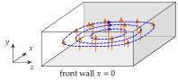
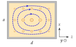
Figure 7.8.5 shows the mode. At all the energy is electric. A quarter period later and all the energy is in . The pattern does not travel: it stays in place and only breathes. The loops of circle round the region where changes fastest, the displacement current (Section 5.2), exactly as the magnetic field of an circuit circles round the current that charges the capacitor. In a cavity the "capacitor" is the middle of the box, where is strong, and the "inductor" is the region near the walls, where is strong. The lines of in a plane are the contours of , since with , a vector tangent to the curves .
Excitation
The field pattern tells us how to feed the mode. A probe (the inner conductor of a coaxial line) through the centre of the broad wall couples to the largest (Figure 7.8.1). A small loop on an end wall couples to the largest , which is there at . An iris in an end wall connects the cavity to a guide that carries TE, whose field has the same transverse pattern.