Section 7.3 · Topic 5 of 11
7.3.5 Field patterns in the cross-section
Figure 7.3.4 shows the transverse fields of the four lowest modes of a guide with . They are drawn at the instant at which the transverse fields are largest in this cross-section, when or , which is out of phase with them, is zero there.
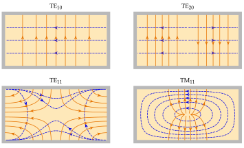
For a TE mode Eq. (7.3.21) gives and : the lines of are the contours of and the lines of cross them at right angles. For a TM mode Eq. (7.3.8) gives and : now the lines of are the contours of . The contours are drawn at equal steps of level, so that their density follows the field strength. In every picture meets the walls at right angles and runs along them, the two boundary conditions of a perfect conductor. The index () counts the half-period variations along ().
The tool below shows the guide of Figure 7.3.3 at , starting with TE. Tap the bars of the mode chart to see each pattern, and move into the green single-mode band, to .
Looking at Figure 7.3.4, which of the four modes are excited by a thin probe parallel to that spans the height of the guide at ?
The probe couples to along the line . TE has its largest there and is excited. TE has on the centre line and is not. TE and TM both have , which changes sign at : the two halves of the probe see equal and opposite fields and the net coupling is zero. A symmetric probe in the middle of the broad side launches a clean TE wave.