Section 7.2 · Topic 2 of 12
7.2.2 TE modes
For the TE case but , and obeys the wave equation
With and the four formulas, Eq. (7.1.11), read
The boundary conditions are
The condition is on the slope of because is proportional to , so on a plate means there. The other tangential component, , is zero everywhere for a TE mode.
The ordinary differential equation
Write out Eq. (7.2.2),
With and ,
Separating the travelling factor, , leaves an ordinary differential equation for the profile across the gap,
It is the equation of a mass on a spring: harmonic in , with "wavenumber" . Its two constants are fixed by the two plates.
Applying the boundary conditions
With the first condition gives
and the second
Each allowed value gives one solution,
The condition says that fits half-periods of a cosine across the gap, with its slope zero on both plates.
gives a constant with no transverse field at all (and the formulas (7.2.3) divide by ): not a wave. The TE modes start at .
The general TE field is the sum of all these solutions. With Eq. (7.2.3) and
the transverse components follow:
Each term in the series is called a mode. The th term is the TE mode. Since , the factor is simply , and a single mode reads
with and .
The electric field of a TE mode points along the plates () and follows , zero on both plates. The magnetic field lies in the plane and closes on itself in loops. The ratio of the transverse fields is the TE wave impedance of Section 7.1.7, as it must be.
Cutoff of the TE modes
The phase constant of TE follows from :
In order to have a propagating (not evanescent) TE mode, must be real:
is called the cutoff frequency of the TE mode. If , the TE mode cannot propagate. It is the general result, Eq. (7.1.14) in Section 7.1, with . The lowest TE mode is TE, with : at cutoff the gap is half a wavelength, . The dispersion diagram of the modes is Figure 7.1.6 in Section 7.1.
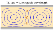
TE is the lowest TE mode, but it is not the dominant mode of the guide. TM has the same cutoff, and the TEM mode (Section 7.2.4) propagates at every frequency: the dominant mode of the parallel-plate guide is TEM.