Section 7.2 · Topic 5 of 12
7.2.5 The TEM mode as a transmission line
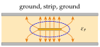
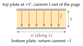
Take a strip of width of the guide, and neglect the fringing at its edges (, Figure 7.2.5).
- The voltage of the top plate relative to the bottom one is .
- The surface current on the top plate, with the normal pointing into the gap, is (the boundary condition of Section 4.2.3), so the current on the strip is . The bottom plate carries .
The ratio does not depend on : it is the characteristic impedance of the line. The inductance and capacitance per unit length are those of the parallel-plate geometry of Chapters 3 and 4.
The TEM mode is exactly the wave on a two-conductor transmission line. Check: and . The power is the same as the integral of over the cross-section .
and are well defined for the TEM mode because its transverse is a static-like field (Section 7.1.3): the integral of from one plate to the other does not depend on the path in the cross-section. TM and TE modes have or , so the voltage between the plates depends on the path, and they have no unique voltage.
A plane pair on a printed board has of FR-4 () and is wide. Find , and , neglecting fringing.
, , and . Check: .
Striplines and printed-board plane pairs. A stripline, a strip buried between two ground planes, and a power and ground plane pair of a printed board are parallel-plate guides. Their wave is TEM: no cutoff, no dispersion, the speed , and an impedance set by the geometry. Higher modes need , far above any signal: of FR-4 () gives .
For FR-4, , that is : the delay budget of every high-speed bus is counted in these units.
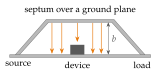
EMC test cells. A large plate, the septum, held over a ground plane and tapered at both ends to a coaxial source and a matched load, creates a known uniform field for immunity tests of car electronics and other equipment (automotive striplines, TEM and GTEM cells).
- The TEM field is uniform only while TM and TE cannot propagate: in air gives , and cells are used well below it, at a few hundred MHz. Bigger cells for bigger devices work only to lower frequencies.
- The field per watt follows from (Worked example 7.2.1).