Section 7.7 · Topic 2 of 10
7.7.2 The quasi-TEM field and the effective permittivity
In the quasi-TEM approximation the line is described by its static capacitance and inductance per unit length. Let be the capacitance per unit length of the real line, with its substrate, and that of the same conductors with the substrate replaced by air. The magnetic field does not see : all materials have , so the inductance is the same as that of the air-filled line. For any TEM line in a homogeneous medium (Section 7.5). For the air-filled line this gives , hence
The real line has and , so its phase velocity and characteristic impedance are and .
where is the impedance of the same strip with the substrate removed.
Fill all of space with a fictitious uniform dielectric of permittivity , chosen so that it gives the same capacitance as the real substrate plus air. The line then is an ordinary TEM line in that medium. is a weighted average: the field in the substrate counts with , the fringing field in the air with .
Figure 7.7.2 shows the computed cross-section field of a line on FR-4. The electric field lines are drawn with the same charge per line, so their density shows where the charge sits: most of it is on the underside of the strip, and most lines run straight down to the ground. The lines refract at the surface of the substrate, exactly as the boundary conditions of Section 3.4.6 require. The magnetic field lines close around the strip. Because does not see the substrate, they are the equipotentials of the air-filled line.
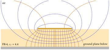
and are electrostatic quantities (Section 3.4.10). Hold the strip at the potential and the ground at , solve Laplace's equation in the cross-section (Section 3.3.5) on a grid, once with the substrate and once without, and obtain each capacitance from the stored energy, . For the FR-4 line of Figure 7.7.2, a grid of spacing and a grounded shield at give and , against and from the closed-form formulas of the next subsections.