Section 4.2 · Topic 4 of 10
4.2.4 Mutual effect of current loops and inductance
The force between two current loops
We shall analyse the force which two current loops apply to each other (Figure 4.2.9). The current flowing along the loop causes a magnetic flux density everywhere in space, in particular at the points of the second loop . Due to the Lorentz law (Section 4.1) the force on a charge moving with the velocity in this field is , and the force on the whole loop is
Since is the current density in the second loop, and for a thin wire is concentrated along the wire,
and in the same way the force of loop 2 on loop 1 is .
Each loop makes a field, and the other loop's current feels it through the Lorentz force. Nothing new is needed: Biot–Savart for the field, for the force. Problem 4.2.1 applies this to two parallel wires and finds the force per unit length , attractive for parallel currents, which is the definition of the ampere that served until 2019.
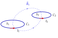
Two long loops seen end-on: drag them and reverse a current to see attraction turn into repulsion.
Mutual inductance
In the same system we observe a magnetic flux due to passing through the surface that is bounded by . We represent this flux by ,
The Biot–Savart law indicates that is directly proportional to : doubling the current doubles the field at every point. Hence must be proportional to as well, and the ratio of the two depends only on the shapes and positions of the loops and on the medium. We define this ratio as the mutual inductance.
is "webers through loop 2 per ampere in loop 1". It measures how strongly the two circuits are linked magnetically. Its unit, the henry, is named after J. Henry, who discovered self induction in 1832.
Flux linkage
A coil usually has many turns. If the number of turns in the second loop is , the flux threads each of them, and what matters for the circuit (as Faraday's law will show in Chapter 5) is the flux counted once for every turn. We define the flux linkage
and the mutual inductance then becomes
It can be shown that always: the flux that loop 1 sends through loop 2 per ampere equals the flux that loop 2 sends through loop 1 per ampere, however different the two loops are. This reciprocity is very useful in practice, because one of the two calculations is nearly always much easier than the other (Worked example 4.2.2, Exercise 4.2.7).
Self inductance
Besides linking , the field of course threads the loop that produces it. Part of the flux of links itself,
and considering the number of turns in loop we write . Finally we define the self inductance.
When only one circuit is considered we write simply .
Self inductance is "flux linkage of a circuit per ampere of its own current". It is a property of the circuit's geometry and of the medium around it, not of the current. A coil with many turns on an iron core has a large because each ampere makes a big flux and that flux is counted times.
Inductance and geometry: how L is actually computed
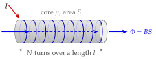
The definitions contain the current, but the current always cancels. The procedure is the same every time (Figure 4.2.10).
- Assume a current in the circuit and find (Ampère's law, with of the core).
- Compute the flux through one turn, .
- Multiply by the number of turns linked, .
- Divide by the current, . The current cancels, so depends on geometry and only. For a mutual inductance, use the current of one circuit and the turns of the other.
For a long solenoid with turns per metre and cross-section on a core of permeability , Ampère's law gives inside (Problem 4.2.3), so that
For a toroid of turns, mean radius and cross-section (Home exercise 4.2.3),
In both, : doubling the turns doubles and doubles the number of linkages.
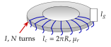
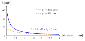
A core with an air gap shows what the boundary conditions do to an inductance. Cut a gap of length into a toroid of mean length (Figure 4.2.11a). The flux density is continuous across the pole faces (), so the same crosses the iron, where , and the gap, where . Ampère's law round the mean path gives
and with ,
The denominator is the length of air that would oppose the flux as much as the whole magnetic path does: the iron path counts only as metres of air ("reluctances in series").
Open the air gap and watch fall and stop depending on , while the allowed current grows.
A coil of turns links the flux when it carries . What is its inductance, and what does it become if the turns are doubled on the same core?
. With turns the same current makes twice the flux and it is linked twice as often: , so .
The flux linkage is , not : a student who computes correctly for an -turn coil (where enters once, through ) and then writes is short by a factor . The inductance of a coil goes as , never as .