Section 4.2 · Topic 5 of 10
4.2.5 Magnetostatic energy
Since moving charges apply forces to each other, work has to be done to establish a set of currents in order: while a current is being built up, the changing flux induces a voltage that opposes the build-up (Faraday's law, Chapter 5), and the source has to push against it. This means there is an energy stored in the system to keep it in order. It is called the stored magnetostatic energy, and it sits in the field, exactly as the electrostatic energy of Section 3.4 does.
the integral extending over all the space where there is a field. The magnetostatic energy density is
For a single circuit the same energy reads
and for two coupled circuits
Every cubic metre of field stores joules. Add it all up and you get , the energy a circuit designer attributes to the inductor. Both views are the same number: Home exercise 4.2.3 checks it for a toroid, where the field is confined to the core and the two integrals are easy.
The field form, Eq. (4.2.25), tells us where the energy is. At the same , the density is times smaller in iron than in air. In a gapped core (Figure 4.2.11) practically all the energy sits in the gap, which is why an inductor meant to store energy, as in a switch-mode power supply, always has a gap (Worked example 4.2.1), and why the force on the armature of an electromagnet is governed by the gap field alone (Exercise 4.2.8). The two-circuit form, Eq. (4.2.28), must be positive for any pair of currents, and this requires , a fact used in Application 4.2.2.
Move and find the minimum of : it stays positive for any .
A inductor carries . How much energy does it store? Where is it, if the core is a closed ferrite toroid, and where if the toroid has a gap?
. In the closed core it is spread through the ferrite. In the gapped core the gap, with times the energy density of the ferrite at the same , holds the energy almost entirely, although it is only of the path (Worked example 4.2.1).
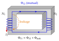
A transformer is two coils, the primary with turns and the secondary with , wound on a common core of high (Figure 4.2.12). Not all of the flux made by winding 1 reaches winding 2: the rest closes through the air around the winding and is called leakage. The fraction that does link is measured by the coupling coefficient
-
always (reciprocity). On a closed high- core the same flux threads both windings. If one ampere-turn makes the flux webers in the core (the permeance of the core, for the toroid of Eq. (4.2.22)), then , , , so that and
-
A mains transformer reaches . That is exactly why : the ideal-transformer law of Chapter 5 is the limit, in which the same flux is linked by both windings and the induced voltage per turn is the same.
-
Leakage is not always a fault. An arc-welding transformer and a microwave-oven transformer are built with a magnetic shunt that deliberately diverts flux, so that the leakage inductance limits the current by itself, without any external resistor.
-
Positive energy for any , in Eq. (4.2.28) requires , which is the proof that . Exercise 4.2.10 shows that the minimum energy at fixed is , which is positive unless .
Worked example 4.2.2 puts numbers in: a secondary of turns wound over the middle quarter of a -turn air-cored solenoid has , and , although every line of the primary crosses the secondary. The coupling is only one half because the short coil's own flux escapes along the rest of the long one.
Shorten the secondary and watch .
Every power supply, from the substation transformer to the charger of a phone. Measuring the series inductance of two coils connected aiding and opposing gives (Exercise 4.2.10), the practical way of finding .
Two coils have , and . What is ? Could be ?
. No: is the largest possible mutual inductance, reached only for perfect coupling.