Section 4.3 · Topic 2 of 10
4.3.2 The magnetic circuit
A core with two windows
Figure 4.3.3 shows an iron core with two windows and two windings, drawn as the currents and that they carry around the windows. The dashed blue line is the mean flux path, the line running along the middle of every branch of the core. It has six corners, labelled A to F, and seven branches: the outer ones , , , , and , and the central limb that the two windows share. Each branch has its own mean length, cross-sectional area and permeability, which for the branch we call , and (labelled in the figure).
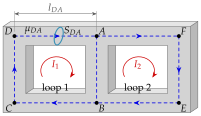
The core guides the flux. Because , almost all lines of stay inside the iron and run along it (we shall return to the "almost" in Section 4.3.8), so inside the branch the field is parallel to the mean path and, if the branch is thin compared with its length, nearly uniform over its cross-section. Two approximations are therefore made:
- in every branch the flux is , with the field on the mean path, and
- the line integral of along the branch is , with the length of the mean path.
One branch at a time
Take the branch . Its flux is
Substituting the constitutive relation of Section 4.2, we can express the field intensity in the branch through its flux:
The contribution of the branch to the circulation of in loop 1 is therefore
Similarly on the branch ,
and on the branches and
Adding the four pieces, exactly as in Eq. (4.3.2), and equating the sum to the current linked by loop 1, we obtain the circulation of around loop 1:
Every term has the same form: the flux of the branch multiplied by a factor that depends only on the geometry and the material of the branch. That factor deserves a name.
The reluctance of a branch of mean length , cross-section and permeability is
The product is the line integral of along the branch, called the magnetic potential drop across the branch, in amperes (or ampere-turns, At).
The unit follows from : amperes divided by webers, and since this is . Long, thin branches of poor material have large reluctance. Short, fat branches of good iron have small reluctance. With reluctances the loop equation (4.3.6) becomes
and the same reasoning around loop 2 (), which links the current , gives
Here is the flux of the central branch counted in the direction , the direction of travel of loop 2, so that while .
The fluxes at the corners
Equations (4.3.8) and (4.3.9) contain seven unknown fluxes, one per branch. The node rule (4.3.3) reduces them to two. Along the outer branches of loop 1 there is no junction, so the same flux runs through , and ,
and in the same way along the outer branches of loop 2,
At the corner A the flux arrives from D, the flux leaves towards F, and the rest goes down the central limb towards B. "What flows in must flow out" at A gives
and the same balance at B is automatically satisfied. Substituting Eqs. (4.3.10) to (4.3.12) into Eqs. (4.3.8) and (4.3.9), and using in the second, we obtain two equations for the two loop fluxes.
Each loop equation is Ampère's law around that loop, with the line integral written branch by branch as . The shared branch enters both equations, with the flux of the other loop subtracted because the two loops run through it in opposite directions.
Equations (4.3.13) and (4.3.14) are the mesh equations of a two-mesh resistor network: "sum of the resistances of the mesh times its own mesh current, minus the shared resistance times the neighbouring mesh current, equals the source in the mesh". Replace resistance by reluctance, mesh current by loop flux and source voltage by current linked, and the magnetic circuit is solved like the electric one.
In Figure 4.3.3 the second winding is removed () and all seven branches have the same reluctance . What is in terms of , and what is ?
From Eq. (4.3.14) with : , so . Then Eq. (4.3.13) gives , i.e. . The central limb carries and the far loop only : the flux prefers the short way round.
Writing for the central limb. Loop 1 runs down the limb (A to B) and loop 2 runs up it (B to A), so the limb carries the difference , exactly like the shared resistor of two meshes carries the difference of the mesh currents. Draw the two loops with their directions before writing the node equation.