Section 4.3 · Topic 8 of 10
4.3.8 Fringing and leakage
Two things have been neglected so far, and both come from the fact that air is a poor insulator for flux (the second failure of the analogy in Section 4.3.3). Figure 4.3.15 shows them on a gapped C-core. In the gap the flux tube spreads: the lines bulge out beyond the pole faces, and this is called fringing. And part of the flux of the coil short-cuts the window from limb to limb without going round the loop at all, and never reaches the gap: this is leakage.
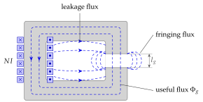
Fringing makes the gap better than the formula says
Outside the gap the flux tube spreads, so the effective cross-section of the gap is larger than the pole area, and the gap reluctance is smaller than . A standard first correction simply adds to each transverse dimension of a rectangular pole (Figure 4.3.16).
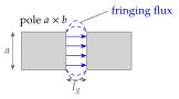
How large is the error? For a C-core with and ,
which raises by about in a circuit dominated by the gap, far too much to ignore in a design. This is why the problems at the end of this section all say "neglect fringing" explicitly.
Switch fringing on at cm² and mm and see fall by 17 %.
Leakage makes the coil worse
Leakage is the other error, and it acts the other way. The flux that jumps the window without going round the loop is a reluctance in parallel with the rest of the circuit, so the coil carries more flux than the useful branch does:
The leakage coefficient tells the designer how much larger the core section must be than the useful flux alone would require. Exercise 4.3.10 works through a circuit with .
Fringing makes the gap better than the formula says, leakage makes the coil worse. Both grow when the gap is long compared with the pole size, which is one more reason to split a long gap into several short ones.
A square pole of side faces a gap. By how much does the fringing correction change ?
, so falls by (Exercise 4.3.9).
The machines of this application carry no magnet and no rotor winding. The rotor is a toothed piece of iron, and the only thing that changes as it turns is the reluctance seen by the excited stator phase. Figure 4.3.17 shows the commonest layout, a switched-reluctance machine with six stator poles and four rotor teeth. The two opposite poles of phase A carry one winding. When it is energised, the flux goes from one pole across the air gap into the nearest rotor tooth, through the rotor body, out of the opposite tooth, across the second gap into the opposite pole, and back through the stator yoke. With the teeth aligned under the poles the two gaps are short and the reluctance of this path is small. With the teeth half-way between the poles the flux has to cross a wide stretch of air and is large.
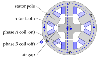


The torque. Let be the rotor angle. The inductance of the excited phase is (Section 4.2), largest in the aligned position, and the energy stored in the circuit is . If the rotor turns by while the current is held constant, the torque is the derivative of the stored energy at constant current (the magnetic counterpart of the constant-voltage force on a dielectric slab in Section 3.4):
The torque has the sign of and the sign of , whatever the sign of : the rotor is always pulled towards the position of minimum reluctance, exactly as a piece of iron is pulled into a coil. Energising the phases A, B and C in turn moves the position of minimum reluctance round the stator, and the rotor follows, by a step for the machine. With a constant current the torque is zero in the aligned position (stable) and in the unaligned position (unstable), and its maximum lies in between (Exercise 4.3.6).
Move the rotor by with the current held fixed by the source. The flux linkage changes by , so Faraday's law makes the source do the work against the induced voltage. The stored energy changes by , which is exactly half of what the source supplied. The other half is the mechanical work , hence . The same "one half" appeared for the capacitor at constant voltage in Section 3.4.
Typical numbers. A small switched-reluctance drive with swinging between (unaligned) and (aligned) over of rotor angle, excited with , develops a peak torque of order per phase, and with a sinusoidal of the same swing the maximum is (Exercise 4.3.6). Since the torque scales with , doubling the current quadruples it, until the teeth saturate.
The switched-reluctance machine ( stator and rotor poles, as in Figure 4.3.17) needs no rare-earth magnet: vacuum cleaners, washing-machine drives and some traction motors use it. The hybrid stepper adds a permanent magnet and fine rotor teeth to reach the familiar step ( steps per revolution) of printers and machine tools.
A U-shaped core with a winding on its yoke, held above a steel plate, is the simplest electromagnet (Figure 4.3.18). The flux driven by runs down one limb, crosses the air gap under the first pole face, passes along the plate, crosses the gap under the second pole face and returns through the second limb and the yoke: a series circuit with the iron of the magnet, the iron of the plate and two air gaps. The plate is pulled towards the poles, and we want the force.
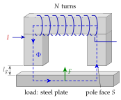
The force on the plate. The energy stored in one gap is per unit volume (Section 4.2), that is in the gap of area and length . Pull the plate away by at constant flux: does not change, the volume of the gap grows by , and the energy added to the field, , is the work done against the magnetic force. Hence the pull on one pole face is
A pole face of area across which the induction is pulls with the pressure . The U-magnet of Figure 4.3.18 has two gaps, so it lifts
Table 4.3.3. The magnetic pressure on a pole face.
| (T) | |||
|---|---|---|---|
| (kPa) | |||
| () |
Typical numbers. Table 4.3.3 evaluates Eq. (4.3.30). The pressure goes as , and iron saturates near , so no electromagnet can pull much more than per , a hard ceiling set by the material, not by the current. Scrap-yard magnets therefore get their tonnage from area, not from field: a disc at already gives about tonnes. The current, on the other hand, sets through the loop rule, in which the gaps dominate (Section 4.3.5): doubling (a rusty or uneven load) at fixed roughly halves and quarters the force, which is why these magnets must sit flat on clean steel. Home exercise 4.3.3 and Exercise 4.3.8 put numbers to a plate and to the collapse of the force at fixed current.
Switch to 'Given I → F' and drag the plate away: the pull collapses roughly as , while the iron takes only a small share.
Writing for the U-magnet. The flux crosses the air twice, once under each pole, so the gap term is , and the force is the sum of the pulls on the two faces. The same "twice" occurs in Problem 4.3.1, where the flux crosses the gap between the two C-cores on both sides.
A pole face of carries . What does it pull with, and how much mass do two such faces hold?
per face, for two, i.e. (Home exercise 4.3.3).
Table 4.3.4. The applications of this section.
| Application | Physics used | Worked out in |
|---|---|---|
| Reluctance and stepper motors | , | Exercise 4.3.6 |
| Electromagnets and lifting magnets | two gaps in series, per gap | Home exercise 4.3.3, Exercise 4.3.8 |