Section 4.3 · Topic 7 of 10
4.3.7 Where magnetic circuits are used
Nearly every electrical machine and many instruments are magnetic circuits: transformers, generators, electric motors, relays, magnetic recording devices and galvanometers all guide the flux of a winding or a magnet through iron and across one or more air gaps. In this subsection we look at three of them with the eyes of Sections 4.3.2 to 4.3.6. Two more, the reluctance motor and the lifting magnet, are the applications at the end of the section.
A remark on air gaps first. Gaps are often cut into cores on purpose, to reduce the effects of saturation. A gap raises the reluctance of the circuit, so a given mmf produces less flux, and the core can be driven with a much larger current before it saturates. The energy stored in the circuit, with (Section 4.2), grows with the current faster than falls, so a gapped core stores more energy before saturation than the same core without a gap, and nearly all of that energy sits in the gap (Exercise 4.3.2). Inductors for switch-mode power supplies are gapped for this reason.
Transformers
A transformer is two windings on one closed magnetic circuit (Figure 4.3.9a). The primary winding of turns, fed with the voltage , drives a flux around the core, and because the core guides nearly all of this flux through the secondary winding of turns, a voltage appears there: the core is the coupling. In a core-type transformer the windings surround the core, as in the figure, while in a shell-type transformer the core surrounds the windings (Figure 4.3.9b). Both are built from stacked laminations to keep the eddy-current loss of Section 4.3.6 small.
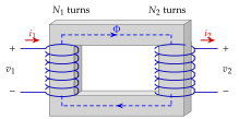


The transformer as a magnetic circuit
Both windings sit on the same flux tube, so the loop equation of Section 4.3.2 has two sources (Figure 4.3.10). With the current directions of Figure 4.3.9a the secondary current opposes the primary one, and
An ideal transformer is the limit (), in which the right-hand side vanishes and . The voltages follow from Faraday's law of induction, on each winding, which belongs to the next chapter and is used here only as a statement: both windings see the same , so the voltages are in the ratio of the turns.
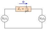
A real core has , so a small magnetising current is left over in the primary to make the flux:
which is seen from the primary as a shunt inductance , the inductance of the primary winding on the core (Section 4.2), with the reactance at the angular frequency . For a sinusoidal flux the voltage has the rms value
the transformer equation. What the designer reads from it is that must stay below saturation. At a fixed voltage a transformer run at instead of needs a proportionally larger product , which is why aircraft use : the same voltage needs an eight times smaller core (Exercise 4.3.5). A poorly stacked joint adds an unwanted to , which lowers and multiplies the magnetising current. Finally, the flux that does not link both coils appears as the leakage inductances and of the two windings, the "per cent impedance" that sets the short-circuit current of the transformer (Section 4.3.8).
A , winding on a core of must keep . How many turns?
turns (Exercise 4.3.5).
Motors
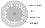
The magnetic circuit of a rotating machine is the stator yoke, the poles, two air gaps and the rotor (Figure 4.3.11a). The field winding on each pole drives a flux that crosses the gap under the north pole, runs through the rotor, crosses the gap again under the south pole and returns through the two halves of the yoke. The gaps are made as small as mechanically possible, to in small machines, because they carry almost all of the reluctance (Section 4.3.5). In the slotted stator and rotor of an induction machine (Figure 4.3.11b) the slots hold the windings, but they also break the iron: the flux has to crowd into the teeth between the slots, which is why the teeth are the first part of the machine to saturate.
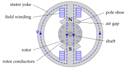
Magnetic recording
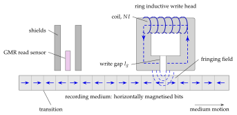
A hard disk stores bits as the direction of magnetisation of small cells of a hard magnetic layer (Figure 4.3.12). The write head is a tiny ring core with a coil and a gap. The flux driven round the ring by the coil current has to cross the write gap, and in doing so it bulges out of the gap as a fringing field (Section 4.3.8) that reaches into the medium passing underneath. Where this field exceeds the coercive field of the medium it sets the magnetisation of the cell, and reversing the coil current reverses the written direction. The bit density of the disk is limited by how well the field can be localised in the write head. A separate read sensor, a magnetoresistive (GMR) element between two soft shields, senses the stray field of the transitions between oppositely magnetised cells.
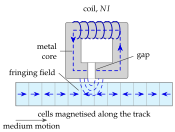
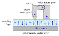
Two ways of arranging the bits are in use (Figure 4.3.13). In longitudinal recording, the older method, the cells are magnetised along the track, as in Figure 4.3.12: the flux of the ring head focuses over the gap and the cell directly below the gap is magnetised. This is also the principle of tape-recorder heads. In perpendicular recording the cells are magnetised perpendicular to the surface of the disk, which lets them be packed more closely. The head has a sharp main pole and a wide return pole, and the disk has a soft magnetic under layer below the recording layer. The flux leaves the sharp pole, passes through the recording layer into the under layer, runs along it and returns through the wide pole: the under layer closes the magnetic circuit through the medium. The gap between the pole tip and the under layer is where the flux is most concentrated, so the cell directly beneath the tip is magnetised perpendicularly, up or down according to the direction of the coil current, and each cell represents a binary 1 or 0.
The write head as a magnetic circuit
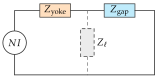
The head is the smallest magnetic circuit in this book, but it obeys exactly the equations of Section 4.3.2 (Figure 4.3.14). Almost all of the reluctance is in the gap, so
while the leakage branch across the yoke steals flux that never reaches the medium. To flip a bit the head must beat the coercivity of the medium, of order to for a perpendicular medium. Allowing for the fall-off of the fringing field below the pole, the head has to produce roughly across a write gap of order :
about turns at . Real drives use several times this, because the yoke, the shields and the leakage take their share (Exercise 4.3.7), and because the field must reverse in well under a nanosecond.
The written transition cannot be sharper than the region over which the fringing field exceeds , and that region scales with and with the spacing between head and medium. At an areal density of order one bit occupies about , for example a track pitch and a bit length. This is the whole content of the sentence "bit density is limited by how well the field can be localised in the write head". Perpendicular recording wins because the soft under layer closes the circuit through the medium, turning a fringing field into a gap field.