Section 3.1 · Topic 4 of 10
3.1.4 Applications of Coulomb's law
Coulomb's law is not only the starting point of a theory but also a working tool of engineering. In every device of Figure 3.1.6 the same inverse-square force is used on purpose, and the engineering question is always the same: how much charge, how far apart, and in which direction does the force point?


Why is the electrostatic force so useful for handling small objects? The answer is a scaling argument. The mass of a particle of size grows as , while the charge it can hold on its surface grows at most as (in practice often more slowly). The charge-to-mass ratio therefore increases as the particle becomes smaller, and for a dust grain, a toner particle or an ink drop a few micrometres across the electric force can exceed the weight by a factor of thousands (Worked example 3.1.2). Charging a particle and applying a field is then enough to send it wherever we want. The six applications below follow this idea, and each is linked to a calculation of this section. They use the electric field , which we define properly in Section 3.1.6. Until then, read simply as "force charge force per unit charge".
A particle carries a charge proportional to its surface area. Its diameter is halved. By what factor do its mass, its charge and its charge-to-mass ratio change?
Mass : divided by . Charge : divided by . So is doubled: smaller particles are easier to steer with a field.
Two further technologies of Figure 3.1.6 deserve a sentence each. In a capacitive touch screen a grid of transparent electrodes forms a small capacitor at every row–column crossing. The field of each capacitor reaches slightly beyond the glass, and a finger (a conductor connected to the surroundings) captures part of it, reducing the mutual capacitance of that crossing, which the controller measures. This is also why the screen does not respond to a gloved finger or an insulating pen. In MEMS devices the Coulomb attraction between interleaved fixed and moving silicon "comb" fingers drives actuators, and, conversely, the change of capacitance when the fingers move is read out in accelerometers and gyroscopes. In electrospray, finally, a liquid held at high voltage at the tip of a capillary is drawn into a sharp cone from which a fine charged jet emerges and breaks into droplets. A charged drop of radius and surface tension can only hold charge up to the Rayleigh limit . As the drop evaporates its charge stays the same, the limit is reached and Coulomb repulsion tears it apart. Electrospray is a standard way of bringing large biomolecules intact into a mass spectrometer.
AIR POLLUTION CONTROL
The flue gas of coal-fired power stations, cement works and steel plants carries fly ash and dust. The grains range from well below a micrometre to a few hundred micrometres, with most of the mass between and , which is too light to be caught by gravity or by inertia. The solution is to give the grains a charge and to collect them with an electric field. An electrostatic precipitator (Figure 3.1.7) does this in three steps.
- Charge. Thin wires hung midway between grounded plates are held at tens of kilovolts negative with respect to the plates (typically to , up to in large units). The very strong field right at the wire surface ionises the gas there (a corona discharge), and the negative ions produced drift outwards and attach themselves to the dust grains.
- Collect. The force (Section 3.1.6) drives each charged grain towards a grounded plate. Because of the drag of the gas the grain quickly reaches a constant migration velocity, of the order of .
- Clean. The dust layer that builds up on the plates is shaken off periodically by mechanical rappers and falls into the hopper below.
Negative corona is preferred in industry because it is more stable and tolerates a higher voltage before sparking over. Negative corona also produces much more ozone, so indoor air cleaners, where ozone matters, use positive corona instead.
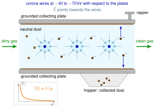
Why a thin wire?
Near the wire the field is that of the infinitely long line charge of Problem 3.1.1,
where is the wire radius and the distance to the plate (the formula is exact for a wire on the axis of a grounded tube and a good model near the wire in a plate-type unit). Because , a wire of radius facing a plate away has a surface field a thousand times larger than the field near the plate. With the numbers of Worked example 3.1.1 the surface field is , while a few centimetres out it is only of order . Ionisation therefore takes place only in a thin shell, a few millimetres thick, around the wire, exactly where it is wanted, and the rest of the gap is a drift region. For thin wires the field at which corona starts is given by Peek's empirical law. For a wire in air it is about , much higher than the breakdown field of a uniform gap.
Efficiency
The collection efficiency is estimated in a first approximation by the Deutsch–Anderson relation
where is the migration velocity, the total collecting area and the volumetric gas flow rate [m³/s]. The relation is idealised (it assumes complete turbulent mixing and one migration velocity for all grains), but it shows the design logic: to increase we either enlarge the plate area or increase the charge on the grains, and with it . Modern precipitators remove more than of the ash mass.
| Quantity | Value |
|---|---|
| Wire voltage | to (up to in large units) |
| Grain size | below to a few hundred (most of the mass to ) |
| Migration velocity | |
| Collection efficiency | more than of the ash mass |
MANUFACTURING
In electrostatic painting the spray gun charges the dry powder (or the liquid paint droplets) as it leaves the nozzle, while the workpiece is grounded (Figure 3.1.8). The charged particles simply follow the field lines (Section 3.1.7), and every field line that leaves the charged cloud must end on the grounded part.
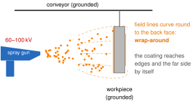
Wrap-around and the Faraday-cage effect
The field lines curve round the edges of the part and close on its back face, so the powder reaches surfaces the spray never points at. This "wrap-around" is one of the main reasons the method is used. The opposite effect appears in inside corners and deep recesses: the conducting part itself partly screens these regions from the field (a relative of the Faraday cage of Section 3.2), and the charged powder lands on the edges before it can enter the recess. In practice the gun voltage is reduced, or the gun is brought closer, for such regions.
Why it is preferred
Powder coating uses no solvent, the overspray can be reclaimed, and a thick film is obtained in a single coat. Until it goes into the oven, the powder stays on the cold part purely by electrostatic adhesion: charge is holding the coating on, with no binder at all. In the oven it melts and cures into the permanent finish.
| Quantity | Value |
|---|---|
| Gun voltage | typically to , low current |
| Powder size | to (average to ) |
| Transfer efficiency | to in the first pass, with reclaim |
| For comparison | plain air spray, no charge: only to of the paint lands on the part |
| Cure | oven, to , minutes |
OFFICE TECHNOLOGY
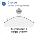
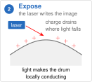
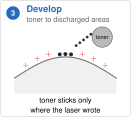
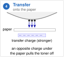
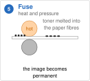
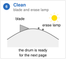
Laser printers and photocopiers use xerography, invented by C. Carlson in 1938 and brought into offices by the Xerox 914 copier (shown in 1959, shipped from 1960). Every printed page passes through the same six steps (Figure 3.1.9), and five of them are purely electrostatic: charge is placed, selectively removed, used to pick up toner, used again to hand the toner over, and wiped off. Only the fifth step, fusing, is thermal.
The key component: a photoconducting drum
The surface of the drum is a photoconductor: an insulator in the dark, a conductor where light falls on it. First the whole surface is charged uniformly by a corona wire or a charge roller. Where the laser writes the image the surface becomes conducting and the charge flows away to the grounded substrate underneath. In this way an optical image is turned into a charge pattern, and from there on everything is Coulomb's law. In laser printers the toner particles ( to ) are charged with the same sign as the drum: they are repelled by the regions that kept their charge and are pushed onto the regions discharged by the laser, helped by the bias voltage of the developer roller (discharged-area development). Classical photocopiers worked the other way round, with toner of the opposite sign attracted to the charged (dark, written) areas. Next, a stronger charge of the opposite sign placed behind the paper pulls the toner over to the sheet. The fuser melts it into the paper fibres and makes the image permanent, and finally a blade and an erase lamp clean the drum for the next page.
Why gravity does not matter
For an toner grain with a charge-to-mass ratio of in a development field of , Worked example 3.1.2 finds
The ratio does not depend on the particle size once is given, and the image does not fall off even when the drum surface faces downwards.
INSTRUMENTATION
A uniform transverse field between two parallel plates exerts a constant force on a charged particle passing between them (Figure 3.1.10). The electron is negative, so the force is , directed against the field. Inside the plates the transverse motion is uniformly accelerated and the path is a parabola. Beyond the plates there is no force and the path is a straight line. Extended backwards, that straight line passes through the centre of the plates, so seen from the screen the particle seems to come from the middle of the deflection region.
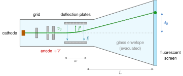
The calculation (done in full in Home exercise 3.1.3) gives the displacement of the spot on the screen. With the length of the plates, the distance from the end of the plates to the screen, and the charge and mass of the particle and its axial speed,
(In Home exercise 3.1.3 the distance to the screen is measured from the beginning of the plates, so there stands for our and the bracket reads .) Three features make this useful:
- The deflection is linear in the plate voltage (since is proportional to it) and free of hysteresis, so the position of the spot is a faithful analogue of the signal applied to the plates. This is the operating principle of the analogue oscilloscope.
- Because the electron is so light, the system responds extremely fast.
- The same principle is used today in electron-beam lithography, ion implanters, electrostatic lenses and mass spectrometers. Television tubes, which needed large deflection angles, used magnetic deflection instead.
PACKAGING & MARKING
The date and batch codes printed on drink cans, medicine boxes and eggs are written by a jet of ink that never stops (Figure 3.1.11). Nothing touches the product.
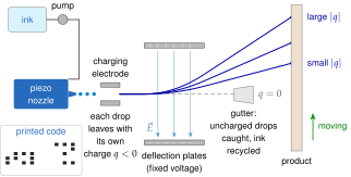
Pressurised ink leaves a fine nozzle as a continuous jet. A jet naturally tends to break up into drops (the Plateau–Rayleigh instability). A piezoelectric element attached to the nozzle forces this break-up to happen at a fixed frequency, so that identical drops are formed. At the instant a drop separates from the jet, the voltage on the surrounding charging electrode sets the charge that drop will carry. The drops then pass between deflection plates held at a fixed voltage. The calculation of Application 3.1.4 (and of Worked example 3.1.3) gives the landing position on the product,
with again measured from the end of the plates. Because the landing position is proportional to the charge on that drop, one pair of plates can write a whole column of a character simply by changing the charge from drop to drop. Uncharged drops are not deflected: they fly into the gutter and the ink is pumped back to the reservoir. A drop of diameter carrying at is moved by , a whole character height, while gravity displaces it by only over the same flight (Worked example 3.1.3), so the print head works in any orientation.
| Quantity | Value |
|---|---|
| Drop size | to |
| Drop rate | drops per second |
| Head-to-product distance | to |
| Product speed | up to several m/s |
FAILURE MECHANISM
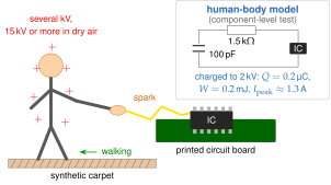
So far the Coulomb force has been our servant, but in electrostatic discharge (ESD) it is the enemy. Walking on a synthetic carpet charges a person by contact (triboelectric) electrification (Figure 3.1.12). The human body behaves like a capacitor of roughly 100 pF with respect to its surroundings, so a fraction of a microcoulomb already raises it to several kilovolts, and to or more in dry air. Touching a grounded object, or the pin of a circuit, then discharges this capacitor in a spark.
Why it is dangerous
The discharge is a charged capacitor emptying through a resistance, and it is described by the circuit relations
For a person charged to the current reaches and the instantaneous power (Worked example 3.1.4). The gate oxide of a MOS transistor, on the other hand, is only a few nanometres thick, and a oxide with a breakdown field of the order of withstands only
A discharge only becomes perceptible to a person at around (audible and visible at higher voltages still), so a event that nobody notices can permanently destroy an integrated circuit.
Standards and countermeasures
Components are rated with the human-body model (HBM: discharged through , standard ANSI/ESDA/JEDEC JS-001), and complete equipment is tested at system level to IEC 61000-4-2 (, ). All countermeasures are charge management: grounding wrist straps, dissipative floors and work surfaces, ionised-air blowers, humidity control, and on-chip protection (clamp) circuits.